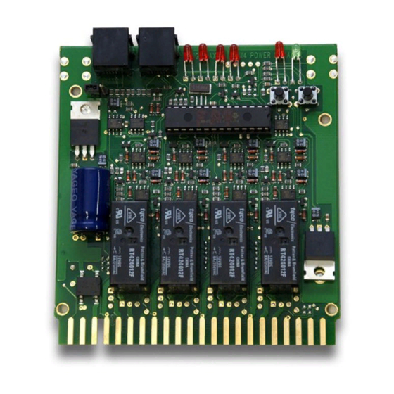
Digitrax PM42 Посібник - Сторінка 9
Переглянути онлайн або завантажити pdf Посібник для Блок управління Digitrax PM42. Digitrax PM42 16 сторінок.

Diagram 2: PM42 Wiring Examples
1 Booster - 4 Auto-Reversing Section
Booster Rail B Pins 7, 11, 15, 19
Booster Rail A Pins 4, 8, 12, 16
Booster Ground
Pins B and/or X
12-18V AC or DC
125mA
Power Supply
NOTE:
To complete auto- reversing set up
you must wire the layout as shown here
and also set the appropriate OpSw
to activate auto- r eversing in your PM42.
See Table IV for appropriate OpSw.
Booster #1 - 2 Short Circuit Managers
Booster #2 - 2 Auto Reverse Controllers
Booster 1, Rail B Pins 15, 19
LocoNet
Booster 1, Rail A Pins 12, 16
Termination
Jumper
Booster 2, Rail B Pins 7, 11
Booster 2, Rail A Pins 4, 8
Booster Ground
Pins B and/or X
12-18 VAC or DC
125mA
Power Supply
NOTE:
To complete auto- reversing set up
you must wire the layout as shown here
and also set the appropriate OpSw
to activate auto- r eversing in your PM42.
See Table IV for appropriate OpSw.
Example C
12-18V AC Pin 3
1 2
A
D
12-18V AC Pin C
PS14
TRACK OUTPUTS
Example D
12-18 VAC Pin 3
1 2
A
D
12-18 VAC Pin C
PS14
Auto-Reverse
8
5 6
9 10
13 14
17 18
H J
M N
S T
5 6
9 10
13 14
17 18
H J
M N
S T
Short Circuit
Controllers
Managers
TRACK OUTPUTS
TOP ROW
20 21 22
44 Pin Connector
BOTTOM ROW
W
X
Y Z
TOP ROW
20 21 22
44 Pin Connector
W
X
Y Z
BOTTOM ROW
