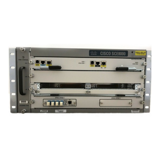
Cisco SCE8000 GBE Посібник із швидкого старту - Сторінка 9
Переглянути онлайн або завантажити pdf Посібник із швидкого старту для Мережеве обладнання Cisco SCE8000 GBE. Cisco SCE8000 GBE 25 сторінок. 10gbe platform
Також для Cisco SCE8000 GBE: Посібник з конфігурації (18 сторінок), Процедури зняття та заміни (36 сторінок), Встановлення (21 сторінок)

Tighten the power supply captive installation screws.
Step 4
Warning
To ensure protective grounding continuity, power supply captive installation screws must be tight.
Because the power requirement of the SCE 8000 does not exceed 1350 W, it is not necessary to connect two pairs
Note
of input wires to each power supply. If you want to connect two pairs of input wires, both pairs of input wires for
one 2700 W DC-input power supply must come from the same battery system (A feed); and both pairs of input
wires for the other power supply must come from another battery system (B feed).
Note
For multiple DC input power supplies, each DC input must be protected by a dedicated circuit breaker or fuse. The
circuit breaker or fuse should be sized according to the power supply input rating and local or national electrical
code requirements.
Step 5
Remove the four screws securing the terminal block cover, and slide the cover off of the terminal block (Figure 6).
Figure 6
DC-Input Front Panel for 2700 W DC-Input Power Supply
1
P W R - 2
7 0 0 - D C
4
1
Captive installation screw
2
DC power cable terminal block
Status LEDs
3
DC power cable terminal block cover
4
Cable holder cover
5
6
Ground
Attach the appropriate lugs to the DC-input wires and ground wire. The wires should be sized according to local and
Step 6
national installation requirements. Use only copper wire. The maximum width of a lug is 0.600 inch (15.2 mm).
Note
For North American installations, use fine-stranded copper conductors rated for 90-degrees Celsius.
2
/4
-V E -1
-V E -1
-V E -2
-V E -2
A L L FA
S T E N E
P R IO R
R S M U
TO O P
S T B E
E R A T IN
F U L LY
G T H E
E N G A
G E D
P O W E
R S U P
P LY
6
8
5
7
3
IN P U T1
IN P U T
O K
2
FA N
48 V -6 0V
O K
O U TP U
T
O K
48 V -6 0V
=4 0A
FA IL
=4 0A
11
9
10
7
Cable holder cover
8
Cable holder
Tie-wrap
9
Cable holder
10
Tie-wrap
11
9
