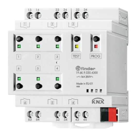
finder 19 Series Посібник - Сторінка 10
Переглянути онлайн або завантажити pdf Посібник для Контролер finder 19 Series. finder 19 Series 17 сторінок. Knx actuator

1.5.9
DPT_Channel X On Delay (s) and DPT_Channel X Off Delay (s) (7.005 TimePeriodSec)
These messages allow to Change run-time the delays set by the PAR_On Delay (s) and PAR_Off Delay (s)
parameters without overwriting them. They only appear on the device descriptor selecting the corresponding
channel function by the PAR_Function parameter.
1.5.10 DPT_Channel X- Blink On Time (s) and DPT_Channel X- Blink Off Time (s) (7.005 TimePeriodSec)
These messages allow to change run-time the blinking periods set by the PAR_Blink On (s) and PAR_Blink
Off (s) parameters without overwriting them. They only appear on the device descriptor selecting the
corresponding channel function by the PAR_Function parameter.
1.6 Enabling Channel logical block
If the PAR_Enable Logic Function
the logical functions are displayed on the device descriptor. The logical operator is selected through the
PAR_Logic Operator parameter. Selections are listed in Table 2.
PAR_Logic
Operator
AND
DPT_Channel X - Logic Input 1 AND DPT_Channel X - Logic Input 2 AND DPT_Channel X
Set ON/OFF
OR
DPT_Channel X - Logic Input 1 OR DPT_Channel X - Logic Input 2 OR DPT_Channel X Set
ON/OFF
XOR
DPT_Channel X - Logic Input 1 XOR DPT_Channel X - Logic Input 2 XOR DPT_Channel X
Set ON/OFF
PORT
FLIP_FLOP (DPT_Channel X Lock PORT, DPT_Channel X Set ON/OFF)
THRESHOLD
SOGLIA (DPT_Channel X
PAR_Comparison method)
(*) The logical value is true if only one of the inputs is true, or both inputs are true.
The channel will change status, according to the configured logical operator. In the case of AND, OR or XOR
selections, switching will occur only if the result of the logical computation on the three inputs DPT_Channel
X Set ON/OFF, DPT_Channel X - Logic Input1 and DPT_Channel X Logic Input 2 is TRUE.
In case the PAR_Logic Operator parameter is set to
ON/OFF message will be processed comparing it with the thresholds set by the PAR_Upper Threshold and
PAR_Lower Threshold parameters
(or with the values for the DPT_Channel X - High Threshold and DPT_Channel X - Low Threshold
messages, once received by the device), in order to build the logical input for channel switching.
If the value of the message exceeds the channel activation threshold (DPT_Channel X
PAR_Upper Threshold), the logical input value will be TRUE. Conversely, if the value of the message exceeds
the channel deactivation threshold (DPT_Channel X
input value will be FALSE.
1.6.1.1
Logical function PORT (FLIP-FLOP)
By setting the PAR_Logic Operator
the DPT_Channel X Lock PORT message the device receives.
FINDER SpA
(*)
Ver. 2018
, the communication objects related to
Value
Set ON/OFF, PAR_Upper Threshold, PAR_Lower Threshold,
Table 2
the value of the DPT_Channel X
Set ON/OFF
KNX Actuator 19.6K
Set ON/OFF
PAR_Lower Threshold), the logical
switching status depends by
Set
10
