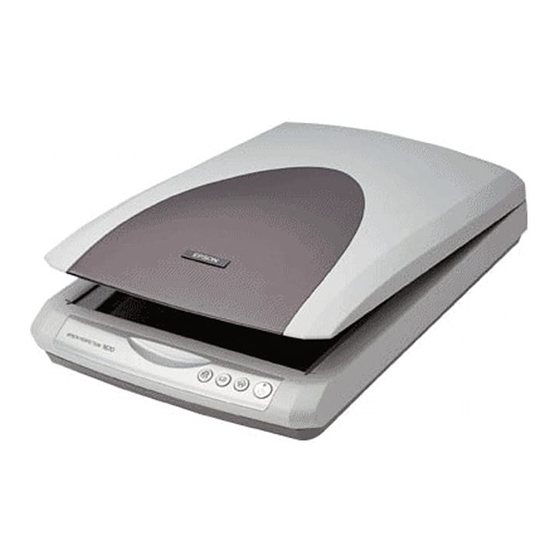
EPSON Perfection 1670 Photo/Perfection 1270
Table 1-5. The Main Unit Does Not Perform Initialization Operation
Step
Cause
Check Point
Any connector has
Check all connectors.
come off.
If there any
1
disconnected
connector?
Table 1-6. The Carriage Unit Does Not Operate
Step
Cause
Check Point
Any connector on the
Has any connector on
1
I/F Board has come
the I/F Board come
off.
off?
• Does the CR Motor
The Carriage
Movement
operate when power
Mechanism is
is switched ON with
defective.
the Upper Housing
of the scanner
2
removed?
• Does the Carriage
Unit move smoothly
with the CR Motor
removed?
The CR Motor is
Disconnect the
defective.
connector on the I/F
Board, and using a
multimeter, measure
the coil resistances
3
between pins 2 and 4
and between pins 1 and
3 on the Motor side.
Are the resistances at
the two points
approximately 4.8Ω?
The I/F Board is
4
faulty.
TROUBLESHOOTING
Judgment
Action
Connect the
Yes
disconnected connector.
Replace the I/F Board.
No
Judgment
Action
Connect the connector.
Yes
Check the Carriage
Movement Mechanism,
and replace the
corresponding part or
disassemble and
No
reassemble the
Mechanism.
Replace the CR Motor.
No
Replace the I/F Board.
---
--
Table 1-7. The Carriage Operates but the Error Is Displayed
Step
Cause
The I/F Board is
1
faulty.
Table 1-8. The Fluorescent Lamp Does Not Turn ON
Step
Cause
The connector on the
1
CCD Board has come
off.
The Fluorescent
Lamp is not
2
connected securely to
the connector on the
Inverter Board.
Replace the Carriage
3
Unit.
The Main Unit I/F
4
Board is faulty.
Table 1-9. The Optional TPU Does Not Operate
Step
Cause
The Cable of the
1
optional TPU Unit
has come off.
The Main Unit I/F
2
Board is faulty.
The TPU Inverter
Board is faulty.
3
Troubleshooting
Check Point
Judgment
Replace the I/F Board.
---
--
Check Point
Judgment
Has the connector on
Replace the Carriage
the CCD Board come
Yes
Unit.
off?
Is the Fluorescent
Replace the Carriage
Lamp connected
Unit.
securely on the Inverter
No
Board?
Is there no error after
Replace the Carriage
replacement of the
Yes
Unit.
Carriage Unit?
Is there no error after
Replace the Carriage
replacement of the
Yes
Unit.
Carriage Unit?
Check Point
Judgment
Has the Connector
Connect the Connector
CN1 of the I/F Board
Yes
CN1 of the I/F Board.
come off?
Replace the I/F Board.
--
--
+24V line: Lamp,
Replace the optional
Motor
TPU Unit.
--
+5V line: Sensor,
Logic Circuit
Revision B
Action
Action
Action
10

