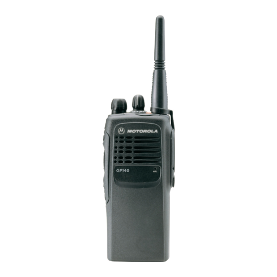
Motorola GP140 Series Базовий посібник з обслуговування - Сторінка 17
Переглянути онлайн або завантажити pdf Базовий посібник з обслуговування для Радіо Motorola GP140 Series. Motorola GP140 Series 46 сторінок. Professional radio, power distribution and controller
Також для Motorola GP140 Series: Посібник користувача (20 сторінок), Сервісна інформація (32 сторінок), Сервісна інформація (30 сторінок), Сервісна інформація (30 сторінок)

Repair Procedures and Techniques Ñ General
4.0
Repair Procedures and Techniques Ñ General
Parts Replacement and Substitution
When damaged parts are replaced, identical parts should be used. If the identical replacement part
is not locally available, check the parts list for the proper Motorola part number and order the part
from the nearest Motorola Communications parts center listed in the ÒPiece PartsÓ section of this
manual.
Rigid Circuit Boards
This family of radios uses bonded, multi-layer, printed circuit boards. Since the inner layers are not
accessible, some special considerations are required when soldering and unsoldering components.
The printed-through holes may interconnect multiple layers of the printed circuit. Therefore, exercise
care to avoid pulling the plated circuit out of the hole.
When soldering near the 20-pin and 40-pin connectors:
Avoid accidentally getting solder in the connector.
Be careful not to form solder bridges between the connector pins.
Examine your work closely for shorts due to solder bridges.
Flexible Circuits
The ßexible circuits are made from a different material than the rigid boards, and require different
soldering techniques. Excessive prolonged heat on a ßexible circuit can damage the material.
Therefore, avoid excessive heat and excessive bending.
For parts replacement, use the ST-1087 Temperature-Controlled Solder Station with a 600-700
degree tip, and use small diameter solder such as ST-633. The smaller size solder will melt faster
and require less heat to be applied to the circuit.
To replace a component on a ßexible circuit:
1.
Grasp with seizers (hemostats) the edge of the ßexible circuit near the part to be removed.
2.
Pull gently.
3.
Apply the tip of the soldering iron to the component connections while pulling with the seizers.
Do not attempt to puddle-out components. Prolonged application of heat may damage the
NOTE
ßexible circuit.
5.0
Disassembling and Reassembling the Radio Ñ General
Since these radios may be disassembled and reassembled with the use of only four (board to
casting) screws, it is important to pay particular attention to the snaps and tabs, and how parts align
with each other.
The following tools are required for disassembling the radio:
Small ßat blade screwdriver
penknife-size screwdriver
TORXª T6 screwdriver
3-3
