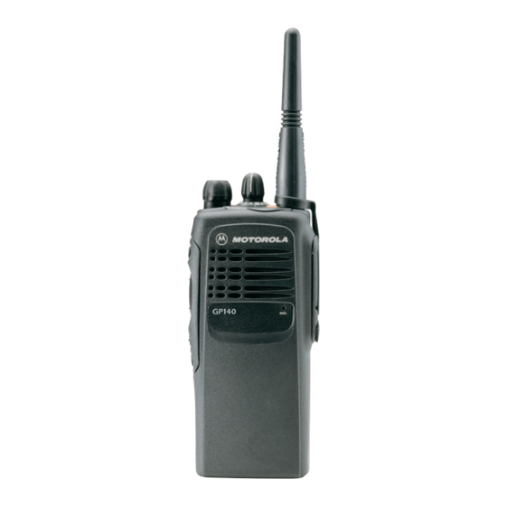
Motorola GP320 Series Сервісна інформація - Сторінка 15
Переглянути онлайн або завантажити pdf Сервісна інформація для Радіо Motorola GP320 Series. Motorola GP320 Series 32 сторінки. Professional radio, power distribution and controller
Також для Motorola GP320 Series: Посібник користувача (26 сторінок), Посібник користувача (26 сторінок), Сервісна інформація (30 сторінок), Сервісна інформація (30 сторінок)

UHF Receiver
3.3
Automatic Gain Control (AGC)
(Refer to the UHF Receiver Front End and Receiver Back End schematic diagrams)
The front end automatic gain control circuit provides automatic reduction of gain, of the front end RF
amplifier via feedback. This action is necessary to prevent overloading of backend circuits. This is
achieved by drawing some of the output power from the RF amplifier output. At high radio
frequencies, capacitor C331 provides a low impedance path to ground for this purpose. CR308 is a
pin diode used for switching the path on or off. A certain amount of forward biasing current is needed
to turn the pin diode on. Transistors Q315 and Q311 provide for this current. When Q315 is turned
on, current flows via R323, collector and emitter of Q315, and R319 before going to ground. Q315 is
an NPN transistor used for switching.
The Radio Signal Strength Indicator (RSS I) voltage signal is used to drive Q315 to saturation, i.e.,
turned on. RSSI is produced by U301 and is proportional to the gain of the RF amplifier and the
input power to the radio.
Resistors R318 and R316 are voltage dividers designed to turn on Q315 at certain RSSI levels. To
turn on Q315, the voltage across R318 must be greater or equal to the voltage across R319 + Vbe.
Capacitor C397 dampens any instability while the AGC is turning on.
Diode D300 is to ensure that C397 only discharges towards the transistor and not back to U301. The
current flowing into the base of Q311, a high current gain PNP transistor, is amplified and fed to the
pin diode to turn it on. Maximum current flowing through the pin is limited by resistors R347 and
R317. Feedback capacitor C333 provides some stability to this high gain stage. Q316, R325, R326,
R327, R338, R339 and R341 make up the temperature compensation circuit for this AGC. RSSI
generated by U301 is lower at cold compared to normal operation at room temperature. Q316 is
designed to turn on only at cold temperature. When Q316 is turned on, current flows through the
collector-emitter junction to ground. Current through R319 and hence voltage across it is reduced.
The turn on voltage is lower and this accommodates for the reduction of the RSSI at cold
temperature.
2-5
