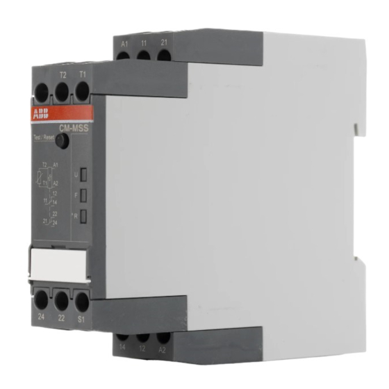
ABB CM-MSS.22 Інструкція з експлуатації та монтажу - Сторінка 5
Переглянути онлайн або завантажити pdf Інструкція з експлуатації та монтажу для Реле ABB CM-MSS.22. ABB CM-MSS.22 8 сторінок. Thermistor motor protection relays
Також для ABB CM-MSS.22: Інструкція з техніки безпеки (20 сторінок)

I
Frontansicht mit Bedienelementen
Betriebszustandsanzeige mit LEDs
U: LED grün - Anzeige Steuerspeisespannung
V Steuerspeisespannung liegt an
F: LED rot
- Fehlermeldung
V Übertemperatur
Reset = Behobenen Fehler bestätigen, Gerät nach Test
zurücksetzen oder Änderung der Konfiguration bestätigen
Achtung:
Bei Schaltströmen > 2 A ist ein seitlicher Geräteabstand von min-
destens 10 mm (0,39 in) einzuhalten.
II
Anschlussdiagramm
Reihenschaltung von 1 bis max. 3 Fühler Typ A pro Fühlerkreis.
Summenkaltwiderstand max. 750 .
Der Fühlerkreis darf nicht geerdet werden.
Überwachungsfunktionen
Das Thermistormotorschutzrelais CM-MSS überwacht die
Wicklungstemperatur und schützt somit den Motor vor
Überhitzung, Überlast und mangelhafter Kühlung. Dieser
muss hierzu mit Typ A Kaltleitertemperaturfühlern (PTC)
ausgestattet sein. Erwärmt sich der Motor über die zulässige
Grenze (Fühlerwiderstand > 2,7 k ), fallen die Ausgangsrelais
ab. Ein Reset ist erst nach Abkühlung des Motors möglich
(Fühlerwiderstand < 1,2 k ).
Reset
CM-MSS.12, CM-MSS.13
Sobald der Messwert nach Beheben eines Fehlers die
Rückschaltschwelle unterschritten hat, führt das Gerät einen
automatischen Reset durch.
CM-MSS.22, CM-MSS.23
Nach Beheben eines Fehlers muss das Gerät zurückgesetzt
werden. Dieser Reset kann manuell über die Reset-Taste,
automatisch durch Brücken von S1-T2 oder extern über einen
Remote-Reset zwischen S1-T2 durchgeführt werden.
Deutsch
I
Front view with operating controls
Betriebszustandsanzeige mit LEDs
U: green LED - Status indication of control supply
F: red LED
Reset = Confirm a rectified fault, reset device after test
routine, or confirm a change of configuration
Attention:
In case of switching currents > 2 A, lateral spacing to other units
has to be min. 10 mm (0.39 in).
II
Connection diagram
Series connection of 1 to max. 3 sensors type A per sensor circuit.
Max. total PTC resistance 750 .
The sensor circuit must not be earthed.
Monitoring functions
The thermistor motor protection relay CM-MSS monitors
the winding temperature and thus protects the motor from
overheating, overload and insufficient cooling.
For this the motor has to be equipped with PTC resistor sensors
type A. If the motor heats up excessively (sensor resistance
> 2.7 k ), the output relays de-energize. A reset is only possible
after cooling down of the motor (sensor resistance < 1.2 k ).
Reset
CM-MSS.12, CM-MSS.13
Once the fault has been rectified and the measured value has
dropped below the release threshold, an automatic reset is
executed.
CM-MSS.22, CM-MSS.23
After rectification of a fault, the device has to be reset. This reset
can be made manually by the Reset button, automatically by
jumpering S1-T2 or externally by a remote reset between S1-T2.
voltage
V Control supply voltage applied
- Fault message
V Overtemperature
English
5
