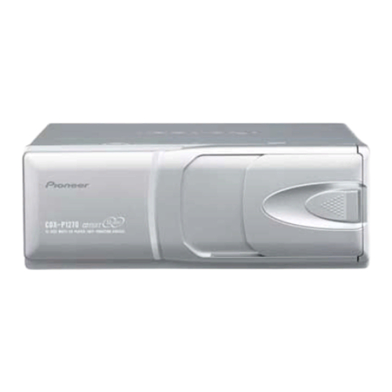
Pioneer CDX-P1270 Навчання з сервісного ремонту - Сторінка 33
Переглянути онлайн або завантажити pdf Навчання з сервісного ремонту для Програвач компакт-дисків Pioneer CDX-P1270. Pioneer CDX-P1270 50 сторінок. Multi-compact disc player
Також для Pioneer CDX-P1270: Посібник користувача (4 сторінок), Посібник користувача (4 сторінок), Посібник користувача (4 сторінок), Посібник користувача (18 сторінок)

- 1. Table of Contents
- 1. 1 Safety Information
- 2. 2 Exploded Views and Parts List
- 3. 3 Block Diagram and Schematic Diagram
- 3. CD Mechanism Module
- 4. 4 Pcb Connection Diagram
- 5. 5 Electrical Parts List
- 6. 6 Adjustment
- 7. 7 General Information
- 7. Diagnosis
- 7. Test Mode
- 7. Disassembly
- 7. Connector Function Description46
- 7. Operational Flow Chart
- 8. 8 Operations and Specifications
- Flow Chart
4
Sourse CD
Power ON
(Adjustment for T.Offset)
TRK
MIN
SEC
00 00 00
Display
Power OFF
BAND
Focus Close/
S Curve Check
TRK
MIN
91 91 91
Display
Power OFF
BAND
T.Close and
F,T AGC and
RF AGC and
Fit Servo
Power OFF
BAND
Power OFF
BAND
< Mechanism test mode in >
9
*9
<ELV,TRAY select>
TYP
*1
Display
Focus Close
*2
Display
00 00 00
(99 99 99)
*3
F.Offset Display
F.Cancel Value = {Top Rank 8bit of Set Value (7F [H] to 80 [H] ) + 128} / 4
*4
Single TR/32TR/100TR
Single TR
*5
Display
9x(8x):91(81)
*6
CRG Move, 100TR Jump Only
6
Test Mode In
Reset
SOURCE
BAND
9
Power ON
(Not adjustment for T.Offset)
TRK
MIN
SEC
99 99 99
Display
9
12
*2
Focus Mode
Select
SEC
TRK
MIN
SEC
0x 0x 0x
Display
7
12
T. Close and
RF AGC Coefficient Display/
Fit Servo
Rough Servo and RF AGC
7
9
*7
F, T, RF AGC/
F, T AGC and
F.Bias Display Select
RF AGC
TRK
MIN
SEC
7
72 00 00
Display
12
FF
*10
*11
<Operation mode
<Shift >
select >
+6dB
+12dB
06 06 06
12 12 12
S Curve Check
01 01 01
RF.Offset Display
F.Cansel Display
= 63 [D] to (32 [D] ) to 00 [D]
32TRK
100TRK
CRG Move
92(82)
93(83)
94(84)
8
*1
RF AMP Gain Select
TRK
MIN
SEC
GG GG GG
7
TRK+
*8
<Tracking Servo Close>
CRG+
TRK
MIN
SEC
TRK
MIN
SEC
00 00 00
00 00 00
or
or
TRK
MIN
SEC
TRK
MIN
SEC
99 99 99
99 99 99
TRK+
9
CRG+
TRK
MIN
SEC
8x 8x 8x
Display
or
TRK
MIN
SEC
9x 9x 9x
12
TRK+
*5
*4
CRG−/TR Jump−
CRG+/TR Jump+
CRG/TR Jump NO.
Select
Display
TRK
REV
BAND
*12
Display
<Shift >
<Mechanism test
mode out >
*7
TRK, MIN, SEC
Voltage of CRG Motor = 2 [V]
*8
*9
ELV motor select
72
00
8ms pulse drive
*10
72
00
48ms pulse drive
72
10
*11
ELV select
TRAY select : TRAY out
*12
ELV select
TRAY select : TRAY in
CDX-P1270
New test mode
12
TRK-
8
*8
*3
Auto Adjustment
CRG−
Display Select
TRK
MIN
SEC
00 00 00
or
TRK
MIN
SEC
99 99 99
TRK-
8
T.Balance
CRG−
Adjustment
TRK
MIN
SEC
8x 8x 8x
or
TRK
MIN
SEC
9x 9x 9x
Tracking
Open
TRK-
8
*4
*6
TRK
MIN
SEC
8x 8x 8x
Display
or
TRK
MIN
SEC
8
9x 9x 9x
Tracking
Open
TRK
MIN
SEC
8x 8x 8x
or
TRK
MIN
SEC
9x 9x 9x
MIN
SEC
F.AGC Gain
T.AGC Gain
(F,T.AGC Gain = (Present Value/Initial Value) × 20)
TRAY motor select
0X
72
10
0X
Display
24ms pulse drive
DC drive
00
72
00
01
72
Display
100ms pulse drive
DC drive
00
72
10
01
72
Display
→
: ELV dowm (Disc 12
1)
→
: ELV up (Disc 1
12)
RF AGC Gain
00
02
10
02
33
