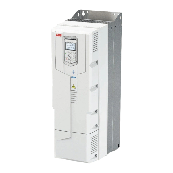
ABB ACQ580-31 Series Посібник зі швидкого встановлення та запуску - Сторінка 2
Переглянути онлайн або завантажити pdf Посібник зі швидкого встановлення та запуску для Блок управління ABB ACQ580-31 Series. ABB ACQ580-31 Series 16 сторінок. Converter modules with electrolytic dc capacitors in the dc link
Також для ABB ACQ580-31 Series: Посібник (16 сторінок)

3. Select the cables and fuses
•
Select the power cables. Obey the local regulations.
•
Input power cable: Use symmetrical shielded cable (VFD cable) for the best EMC performance. NEC installations:
Conduit with continuous conductivity is also allowed and must be grounded on both ends.
•
Motor cable: ABB recommends symmetrically shielded VFD motor cable to reduce bearing current and wear and
stress on motor insulation and to provide the best EMC performance. Although not recommended, conductors
inside continuously conductive conduit is allowed in NEC installations. Ground conduit on both ends.
•
Power cable types: IEC installations: Use copper cables. Aluminum cables can only be used with frame sizes R6 and
R8, except the biggest R8. NEC installations: Only copper conductors are allowed.
•
Current rating: max. load current.
•
Voltage rating (minimum): IEC installations: 600 V AC cable is accepted for up to 500 V AC. NEC installations: 1000 V
AC for 480 V AC motors. 600 V AC for 480 V AC power line.
•
Temperature rating: IEC installations: Select a cable rated for at least 70 °C maximum permissible temperature of
conductor in continuous use. NEC installations: Use 75 °C conductors minimum. Insulation temperature can be
higher as long as the ampacity is based on 75 °C conductors.
•
Select the control cables.
•
Use double-shielded twisted-pair cable for analog signals. Use double-shielded or single-shielded cable for the
digital, relay and I/O signals. Do not run 24 V and 115/230 V signals in the same cable.
•
Protect the drive and input power cable with the correct fuses. See
4. Examine the installation site
Examine the drive installation site. Make sure that:
•
The installation site is sufficiently ventilated or cooled to remove heat from the drive.
•
The ambient conditions of the drive meet the specifications. See
•
The wall behind the drive and the material above and below the unit is of non-flammable material.
•
The installation surface is as close to vertical as possible and strong enough to support the drive.
•
There is sufficient free space around the drive for cooling, maintenance and operation. For the minimum free space
requirements, refer to
Dimensions, weights and free space requirements
•
There are no sources of strong magnetic fields such as high-current single-core conductors or contactor coils near the
drive. A strong magnetic field can cause interference or inaccuracy in the operation of the drive.
5. Install the drive on the wall
Select fasteners that comply with local requirements applicable to wall surface materials, drive weight and application. For
Dimensions, weights and free space requirements
drive weights, refer to
mm
a
474
b
160
1
R3
in
18.66
6.29
Ratings, fuses and typical power cables
Ambient conditions
.
.
2
b
R6
mm
in
753
29.64
213
8.38
.
.
4
3
R3: M5 (#10)
R6: M8 (5/16")
R8: M8 (5/16")
R8
mm
in
945
37.20
263
10.35
2
