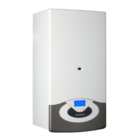
Ariston genus evo 30 CF Інструкція з монтажу та обслуговування - Сторінка 14
Переглянути онлайн або завантажити pdf Інструкція з монтажу та обслуговування для Котел Ariston genus evo 30 CF. Ariston genus evo 30 CF 48 сторінок. Wall-hung
Також для Ariston genus evo 30 CF: Посібник користувача (16 сторінок)

installazione
Schema idraulico
Legenda:
1. Scambiatore primario
3. Sonda mandata
riscaldamento
4. Bruciatore
5. Elettrodi di accensione
6. Valvola gas
7. Scambiatore secondario
8. Valvola di sicurezza 3 bar
10. By-pass automatico
11. Rubinetto svuotamento
12. Rubinetto di
riempimento
Collegamento condotti scarico fumi
La caldaia dovrà essere collegata ad un sistema di evacuazione fumi
rispondente alle normative vigenti. Verifi care la corretta evacuazione
dei prodotti della combustione misurando il contenuto di CO
portata termica nominale. Tale valore non deve essere superiore a
quello riportato nella tabella Dati Tecnici.
Se il valore risultasse superiore, far verifi care l'effi cienza del sistema
scarico fumi.
Nel caso in cui non sia possibile riportare il valore del CO
indicato in tabella Dati Tecnici non mettere in funzione l'apparecchio.
IMPORTANTE
I condotti scarico fumi non devono essere a contatto o nelle vicinanze
di materiali infi ammabili e non devono attraversare strutture edili o
pareti di materiale infi ammabile.
ATTENZIONE
Assicurarsi che i passaggi di scarico e ventilazione non
siano ostruiti.
Assicurarsi che i condotti di scarico fumi non abbiano
perdite
14
1
3
5
7
8
10
11
C
A
B
13. Filtro circuito
riscaldamento
14. Flussimetro sanitario
15. Valvola deviatrice
motorizzata
16. Manometro
17. Sensore di pressione
18. Circolatore modulante
con disareatore
19. Elettrodo rilevazione
20. Vaso espansione
21. Sonda ritorno
riscaldamento
alla
2
a quanto
2
installation
Water circuit diagram
21
20
19
18
17
16
15
14
13
12
D E
Legend:
1. Main Heat Exchanger
3. Central Heating Flow
Temperature Probe
4. Burner
5. Ignition Electrodes
6. Gas Valve
7. Secondary Exchanger
8. Safety valve
10. Automatic By-pass
11. Drain valve
12. Filling valve
Connection of fl ue gas discharge ducts
The boiler must be connected to a fl ue gas discharge system that
complies with the regulations in force. Make sure that the combustion
products are properly expelled by measuring the CO2 content at the
nominal heat output. This value should not exceed that indicated in
the Technical Data table.
If the value is greater, check the effi ciency of the fl ue gas exhaust
system.
If it is not possible to bring the CO2 value within the limit indicated in
the Technical Data table, do not start the appliance.
IMPORTANT
The fl ue gas exhaust ducts must not be in contact with or placed near
fl ammable materials, and must not cross building structures or walls
made using fl ammable material.
WARNING
Make sure that the fl ue gas exhaust and ventilation ducts
are not obstructed.
Make sure that there are no leaks along the fl ue gas
exhaust ducts.
13. Central Heating Filter
14. D.H.W. Flow Switch
15. Diverter valve
16. Pressure Gauge
17. Water pressure sensor
18. Modulating Circulation
Pump with air release
valve
19. Detection electrode
20. Expansion vessel
21. Central Heating Return
Temperature Probe
