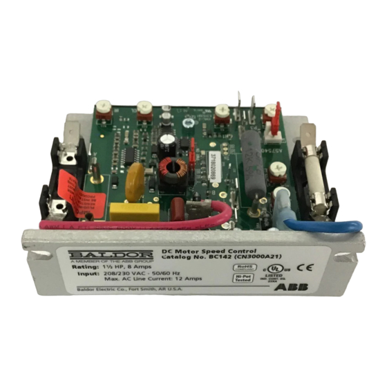
ABB Baldor BC142-6 Посібник з монтажу та експлуатації - Сторінка 17
Переглянути онлайн або завантажити pdf Посібник з монтажу та експлуатації для Блок управління ABB Baldor BC142-6. ABB Baldor BC142-6 20 сторінок. Dc control

Note: Readjusting the MIN Trimpot will affect the maximum speed setting. Therefore, it is necessary
to readjust the MAX Trimpot if readjusting the MIN Trimpot. It may be necessary to repeat these
adjustments until both the minimum and maximum speeds are set to the desired levels.
Maximum Speed Trimpot (MAX)
The MAX Trimpot sets the maximum speed of the motor when the Main Speed Potentiometer is
set fully clockwise. The MAX Trimpot is factory set to 100 % of base motor speed. To increase the
maximum speed, rotate the MAX Trimpot clockwise. To decrease the maximum speed, rotate the MAX
Trimpot counterclockwise.
Do not set the maximum speed above the rated motor RPM since unstable motor operation may occur.
Current Limit Trimpot (CL)
The CL Trimpot sets the current limit (overload), which limits the maximum current (torque) to the
motor. The CL also limits the AC line inrush current to a safe level during startup. The CL Trimpot
is factory set to 1.5 times the full load rating of the motor. To increase the current limit, rotate the
CL Trimpot clockwise. To decrease the current limit, rotate the CL Trimpot counterclockwise. Some
applications require a lower torque limiting value so as not to damage the process material or the
drive train.
Note: The correct value Plug-In Horsepower Resistor® must be installed for the CL to operate properly.
Calibration of the CL Trimpot is normally not required when the proper Plug-In Horsepower
Resistor® is installed.
Caution:
Adjusting the CL above 150% of motor rating can cause overheating and demagnetization of some PM
motors. Consult motor manufacturer.
To Recalibrate the CL Trimpot:
1. Disconnect the AC power and wire a DC ammeter in series with either motor armature lead.
Note: If only an AC ammeter is available, wire it in series with either AC line input lead.
2. Set the Main Speed Potentiometer to approximately 30 - 50 % clockwise position.
3. Set the CL Trimpot fully counterclockwise.
4. Load the motor shaft in accordance with application requirements.
5. Apply power and the CL LED will illuminate red. Rotate the CL Trimpot clockwise until the desired
current reading is observed on the ammeter. Factory Current Limit setting is 1.5 times the full load
rating of the motor (with a DC ammeter wired in series with the motor armature). If using an AC
ammeter wired in the AC line input, the factory Current Limit setting will read 0.75 times the full
load rating of the motor.
Note: On cyclical loads, it may be normal for the CL LED to momentarily flash.
IR Compensation Trimpot (IR)
The IR Trimpot sets the amount of compensating voltage required to keep the motor speed constant
under changing loads. If the load does not vary substantially, the IR Trimpot may be set to a minimum
level (approximately 1/4 of full clockwise rotation). The IR Trimpot is factory set to provide 3 Volts of
compensation for controls with 90 Volt DC output and 6 Volts of compensation for controls with 180
VDC output. To increase the amount of compensating voltage, rotate the IR Trimpot clockwise. To
decrease the amount of compensating voltage, rotate the IR Trimpot counterclockwise.
Notes:
1. The correct value Plug-In Horsepower Resistor® must be installed for the IR Compensation to
operate properly. Calibration of the IR Trimpot is normally not required when the proper Plug-In
Horsepower Resistor® is installed.
2. Excessive IR Compensation will cause the motor to become unstable, which causes cogging.
3. For tachometer feedback applications, set the IR Trimpot fully counterclockwise.
To Recalibrate the IR Trimpot:
1. Set the IR Trimpot to approximately 25% rotation.
2. Run the motor unloaded at approximately 1/3 speed and record the RPMs.
2-10
MN704
