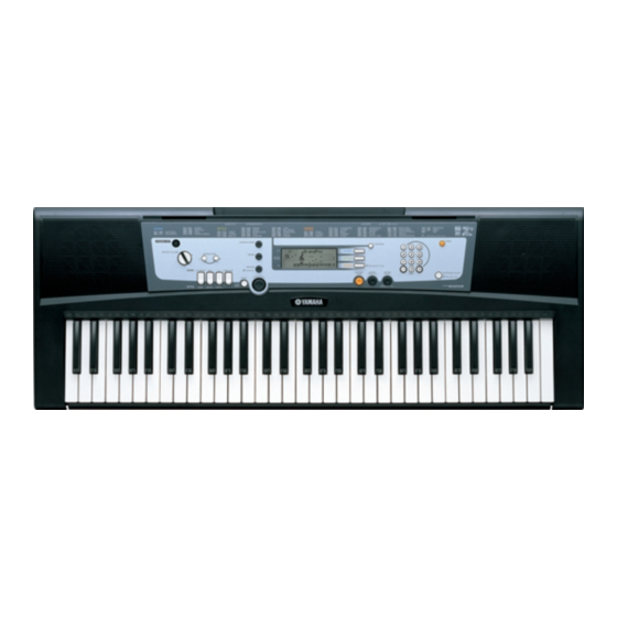
Yamaha Portatone PSR-E213 Посібник з експлуатації - Сторінка 10
Переглянути онлайн або завантажити pdf Посібник з експлуатації для Електронна клавіатура Yamaha Portatone PSR-E213. Yamaha Portatone PSR-E213 37 сторінок.

PSR-E213/YPT-210
2.
DMLCD Circuit Board, LCD Display
(Time required: About 3 minutes each)
2-1
Remove the lower case assembly. (See procedure 1)
2-2
DMLCD Circuit Board
2-2-1 Remove the eight (8) screws marked [160A]. The
DMLCD circuit board can then be removed. (Fig. 2)
* When attaching or removing the MK wire (DMLCD cir-
cuit board: CN501), insert or pull the MK wire while press-
ing the both side of the connector downward. (Fig. 3)
* When installing the DMLCD circuit board, tighten the
screws 1 through 8 in numerical order. (Fig. 2)
2-3
LCD Display
2-3-1 Remove the DMLCD circuit board. (See procedure 2-2)
2-3-2 Remove the rubber connector and LCD holder A.
The LCD display can then be removed. (Fig. 4)
* When attaching the rubber connector, set the con-
ductive part to face inside. (Fig. 4)
3.
PNAM Circuit Board (1/2, 2/2)
(Time required: About 3 minutes each)
3-1
Remove the lower case assembly. (See procedure 1)
3-2
PNAM Circuit Board 1/2
3-2-1 Remove the eleven (11) screws marked [160B]. The
PNAM circuit board 1/2 can then be removed. (Fig. 2)
3-3
PNAM Circuit Board 2/2
3-3-1 Remove the eight (8) screws marked [160C]. The PNAM
circuit board 2/2 can then be removed. (Fig. 2)
*
When replacing the PNAM circuit board, remove the
wiring assembly GND1 from the old PNAM circuit board
and then attach it on the new PNAM circuit board if the
wiring assembly GND1 is originally installed. For details,
refer to page 18. (U only)
4.
Speaker (Time required: About 2 minutes)
4-1
Remove the lower case assembly. (See procedure 1)
4-2
Remove the four (4) screws marked [30]. The speaker
can then be removed. (Fig. 2)
* The right and left speakers can be removed in the
same manner.
5.
Lower Case Keyboard Assembly
(Time required: About 3 minutes)
5-1
Remove the lower case assembly. (See procedure 1)
5-2
Remove the two (2) screws marked [250B] and screw
marked [260B]. The lower case keyboard assembly can
then be removed. (Fig. 2)
* When attaching or removing the MK wire (DMLCD cir-
cuit board: CN501), insert or pull the MK wire while press-
ing the both side of the connector downward. (Fig. 3)
10
2.
DMLCDシート、液晶ディスプレイ
(所要時間:各約3分)
2-1
下ケースAss'yを外します。 (1項参照)
2-2
DMLCDシート
2-2-1 [160A] のネジ8本を外して、DMLCDシートを外しま
す。 (図 2)
※ MK線材 (DMLCDシート:CN501) の取り付け、取り
外しは、コネクタの両脇を下に押しながらMK線材
を抜き差しします。 (図 3)
※ DMLCDシートを取り付けるときは、1から8の順で
ネジを締めてください。 (図 2)
2-3
液晶ディスプレイ
2-3-1
DMLCDシートを外します。 (2-2項参照)
2-3-2
ゴムコネクタとLCDホルダーAを外して、液晶ディスプ
レイを外します。 (図 4)
※ ゴムコネクタ−を取り付けるときは導電部を内側の
向きにしてください。 (図 4)
3.
PNAMシート (1/2、2/2)
(所要時間:各約3分)
3-1
下ケースAss'yを外します。 (1項参照)
3-2
PNAMシート1/2
3-2-1 [160B] のネジ11本を外して、PNAMシート1/2を外しま
す。 (図 2)
3-3
PNAMシート2/2
3-3-1 [160C] のネジ8本を外して、PNAMシート2/2を外しま
す。 (図 2)
4.
スピーカ (所要時間:約2分)
4-1
下ケースAss'yを外します。 (1項参照)
4-2
[30] のネジ4本を外して、スピーカーを外します。 (図 2)
※ 左右のスピーカは同じように外せます。
5.
下ケース鍵盤Ass'y ( 所要時間:約3分)
5-1
下ケースAss'y を外します。 (1項参照)
5-2
[250B] のネジ2本と、 [260B] のネジ1本を外して、下
ケース鍵盤Ass'yを外します。 (図 2)
※ MK線材 (DMLCDシート:CN501) の取り付け、取り
外しは、コネクタの両脇を下に押しながらMK線材
を抜き差しします。 (図 3)
