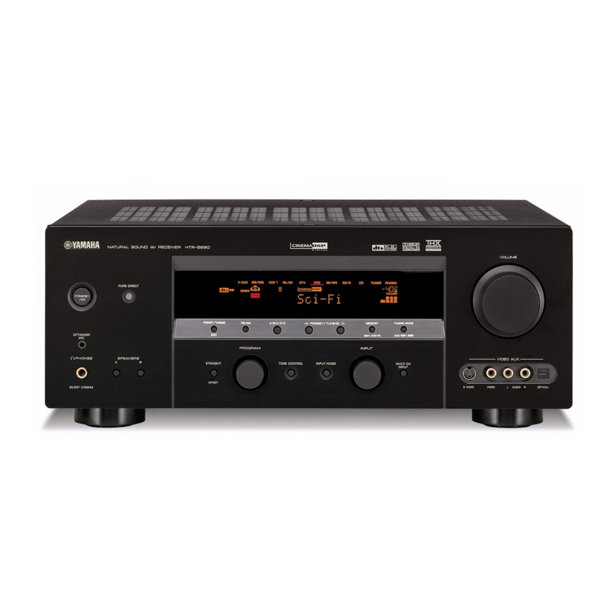
Yamaha htr-5890 Посібник з експлуатації - Сторінка 10
Переглянути онлайн або завантажити pdf Посібник з експлуатації для Приймач Yamaha htr-5890. Yamaha htr-5890 41 сторінка.

- 1. Table of Contents
- 2. Service Manual
- 3. Important Notice
- 4. To Service Personnel
- 5. Front Panel
- 6. Remote Control Panel
- 7. Rear Panels
- 8. Specifications
- 9. Internal View
- 10. Disassembly Procedures
- 11. Updating Firmware
- 12. Self Diagnosis Function (Diag)
- 13. Amp Adjustment
- 14. Display Data
- 15. IC Data
- 16. Remote Control
HTR-5890
3. Removal of DSP P.C.B.
a. Remove 2 screws (5) and then remove the Support.
(Fig. 4)
b. Remove 5 screws (6) and then remove the Bracket.
(Fig. 4)
c. Remove 1 screw (7). (Fig. 4)
d. Remove 8 screws (8). (Fig. 5)
e. Remove CB501, CB503 ~ CB505. (Fig. 3)
f. Remove the DSP P.C.B. and Shield Case upward. (Fig.
4)
4. Removal of VIDEO (2) P.C.B.
a. Remove 1 screw (9). (Fig. 4)
b. Remove CB554, CB555 and CB558. (Fig. 3)
c. Remove the VIDEO (2) P.C.B. which is connected
directly to the lower P.C.B. with connectors. (Fig. 4)
10
CB555
9
VIDEO (2) P.C.B.
Shield Case
DSP P.C.B.
5
6
6
6
7
6
Fig. 4
Fig. 5
CB558
CB554
CB504
CB505
CB501
CB503
Fig. 3
Support
6
Bracket
