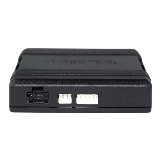
Directechs DB3 Інструкція з експлуатації - Сторінка 7
Переглянути онлайн або завантажити pdf Інструкція з експлуатації для Автомобільна електроніка Directechs DB3. Directechs DB3 17 сторінок. 2011 subaru outback - 403.subaru2 1.25
Також для Directechs DB3: Посібник з монтажу (20 сторінок), Посібник з монтажу (19 сторінок), Посібник з монтажу (19 сторінок), Посібник з монтажу (20 сторінок), Посібник з монтажу (10 сторінок)

Vehicle connections
The connection information listed below is specific to the 2014 Mazda 3 (Smart Key). Refer to "Pre-installation and application warnings" for a list of important notes.
Data 14-pin blue connector (H1)
Module
Conn./Pin
Color
H1/1
Light Green
H1/2
Violet/Yellow
H1/3
Tan/Black
H1/4
Tan
H1/5
Orange/Green
H1/6
Orange/Brown
H1/7
Brown
H1/8
Yellow
H1/9
Orange/Yellow
H1/10
Orange/Red
H1/11
Yellow/Red
H1/12
Brown/Red
H1/13
Red
H1/14
Black
Output 12-pin red connector (H2)
Module
Conn./Pin
Color
H2/1
Black/White
H2/2
Green/Black
H2/3
Green/White
H2/4
Red/Black
H2/5
Violet/White
H2/6
Gray
H2/7
Gray/Black
H2/8
Violet/Green
H2/9
Violet/Brown
H2/10
Yellow/Black
H2/11
Orange/Black
H2/12
Blue/Red
7
403.MA3 2.42.104 2014 Mazda 3 (Smart Key)
©2023 Directed. All rights
Description
No Connection
No Connection
(DATA) HS CAN High
(DATA) HS CAN Low
(DATA) HS CAN High
(DATA) HS CAN Low
[2]
Relay N.O. - (-) Parking Light Output
Relay COM. - Parking lights Interrupt (vehicle side)
Relay N.C. - Parking lights Interrupt (connector side)
Relay N.C. - Ignition interrupt (connector side)
Relay COM. - Ignition interrupt (vehicle side)
Relay N.O. - No connection
(+) 12 Volt Input
(-) Ground
Description
No connection
(-) PTS Output
No Connection
No Connection
No connection
(+) Ignition Output
(+) Accessory Output
No Connection
(+) Starter Output
No connection
(Data) Keyless Data
No connection
Connects To
Wire Location
No Connection
No Connection
Start Stop Unit in steering column, white 24 pin plug, pin 7
Start Stop Unit in steering column, white 24 pin plug, pin 8
No Connection
No Connection
Parking Light Switch Assembly inside steering column, white 6 pin plug, pin 3
Connection required when not supported in data.
[2]
Parking Light Switch Assembly inside steering column, white 6 pin plug, pin 4
Connection required when not supported in data.
[2]
Parking Light Switch Assembly inside steering column, white 6 pin plug, pin 4
Connection required when not supported in data.
Start Stop Unit in steering column, white 32 pin plug, pin 17
Start Stop Unit in steering column, white 32 pin plug, pin 17
No Connection
Driver Kick Fuse Box, rear, white 1 pin plug, pin 1
Connects To
Wire Location
No Connection
Start Stop Unit in steering column, white 32 pin plug, pin 20
No Connection
No Connection
No Connection
Start Stop Unit in steering column, white 24 pin plug, pin 10
Start Stop Unit in steering column, white 24 pin plug, pin 14
No Connection
Start Stop Unit in steering column, white 24 pin plug, pin 23
No Connection
Start Stop Unit in steering column, white 32 pin plug, pin 9
No Connection
(+/-)
Wire Color
Data
White (HS CAN)
Data
Red (HS CAN)
-
Yellow
Cut
Green
Cut
Green
Cut
Violet
Cut
Violet
+
White (50A)
(chassis ground)
(+/-)
Wire Color
-
Brown
+
Lt. Green
+
Brown
+
Green
Data
Lt. Blue
