Directed Xpresskit DBALL2 Посібник з монтажу - Сторінка 6

Переглянути онлайн або завантажити pdf Посібник з монтажу для За замками Directed Xpresskit DBALL2. Directed Xpresskit DBALL2 16 сторінок. Ford5 remote start ready (rsr) installation
Також для Directed Xpresskit DBALL2: Посібник з монтажу (12 сторінок), Посібник з монтажу (19 сторінок), Посібник з монтажу (18 сторінок), Посібник (14 сторінок), Посібник з монтажу (13 сторінок), Посібник з монтажу (14 сторінок), Посібник з монтажу (19 сторінок), Посібник з монтажу (16 сторінок), Посібник з монтажу (20 сторінок), Посібник з монтажу (15 сторінок), Посібник зі встановлення та короткий довідник (16 сторінок), Посібник з монтажу (18 сторінок), Посібник з монтажу (18 сторінок), Посібник з монтажу (16 сторінок), Посібник (19 сторінок)
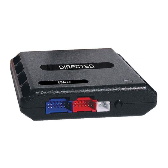
Directed Xpresskit DBALL2 Посібник з монтажу
Platform: DBALL2
Firmware:
CHRYSLER8 Remote Start Ready (RSR) Installation

SmartStart/XL202 Installation Notes

The DBALL2 Remote Start Ready (RSR) solution offers three (3) configuration options to control your system: 3x OEM Lock
Remote Start Activation, RF Kits or SmartStart (all sold separately). This section provides specific installation information for
SmartStart and XL202.
SmartStart Revision A
SmartStart is optional and not included. It MUST be purchased separately.
Configuration Wires (White & Brown or Blue)
DBALL/
DBALL2
CABLE
D2D (4 pins, white)
The modules must be connected in a specific order. Refer to the Module Programming section for more information.
SmartStart Revision B
SmartStart is optional and not included. It MUST be purchased separately.
DBALL/
DBALL2
CABLE
D2D (4 pins, white)
The modules must be connected in a specific order. Refer to the Module Programming section for more information.
RF Kit
The optional XL202 and antenna are not included and MUST be purchased separately.
DBALL/
DBALL2
XOVER
1. Use the D2D Crossover (XOVER) cable that is provided with XL202, and NOT the one in the DBALL package.
2. The modules must be connected in a specific order. Refer to the Module Programming section for more information.
RF Kit & PKE Combination
Refer to the Passive Keyless Entry (PKE) Installation Guide (N2102T) for detailed wiring information.
RF Kit, PKE & SmartStart BT Combination
Refer to the Passive Keyless Entry (PKE) Installation Guide (N2102T) for detailed wiring information.
Cut Brown or Blue Loop
4 pins
2 pins,
not used
Configuration Wires (Gray & White)
Connect Gray wire to (-) Ground
5 pins
4 pins
2 pins,
not used
LED
LED
XL202
Prog.
Button
OR
SmartStart
LED
THIS SIDE UP
Rev.: 20151126
Page 6
© 2015 Directed. All rights reserved.