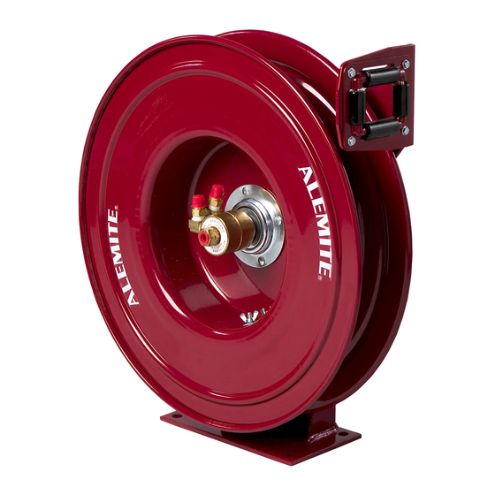
Alemite 7338-C Посібник з експлуатації - Сторінка 5
Переглянути онлайн або завантажити pdf Посібник з експлуатації для Інструменти Alemite 7338-C. Alemite 7338-C 12 сторінок. Severe-duty welding hose reel

Severe-Duty Welding Hose Reel
Overhaul
NOTE: Refer to Figure 2 for component
identification on all overhaul procedures.
WARNING
Release all pressure within the system
prior to performing any overhaul procedure.
• Disconnect each delivery connecting hose at
the reel.
Read each step of the instructions carefully. Make
sure a proper understanding is achieved before
proceeding.
Disassembly
IMPORTANT: Prior to disassembly, release
tension on the power spring.
1. Pull on the delivery hose to unlatch the reel.
2. Allow the hose to retract onto the reel.
3. Turn the reel in the same direction until the power
spring bypasses Spring Arbor (44).
• A pronounced "click" will sound.
4. Unwrap each coil of hose from Sheave Assembly (16).
5. Remove Wing Nuts (14) and Washers (13) that secure
U-Bolt (15) to the Sheave Assembly.
• Remove the U-Bolt from the Sheave.
Sheave and Power Spring Assembly
6. Remove the Swivel Shaft (with attached components)
from Shaft and Flange Assembly (40).
7. Remove Retaining Ring (11) and Washer (12) from the
Shaft and Flange Assembly.
• Use care not to mar the surface of the shaft.
8. Remove the Sheave and Power Spring Assembly from
the Shaft and Flange Assembly.
Note: Perform steps 9-11 only if replacing Sheave
Assembly (16) or Power Spring Assembly (36).
9. Position the Sheave and Power Spring Assembly with
the ratchet upward.
Alemite Corporation
WARNING
Do not disassemble the Power Spring Assembly.
The spring within the case is under high-tension.
Personal injury can occur.
10. Drill out Rivets (45) that secure Power Spring
Assembly to the Sheave Assembly.
• Remove the Power Spring Assembly from the
Sheave Assembly.
11. Remove Gasket (25) from the Sheave Assembly.
12. Remove O-Ring (27) from the Power Spring
Assembly.
Base and Hose Guide Assembly
13. Remove O-Ring (41) from the Shaft and Flange
Assembly.
14. Remove Spring Arbor (44) from the Shaft and Flange
Assembly.
• Remove Woodruff Key (43).
15. Remove Ball Bearing (42) from the Shaft and Flange
Assembly.
16. Remove additional O-Ring (41) from the Shaft and
Flange Assembly.
17. Remove Nuts (30) that secure Hose Guide Arm (29) to
Base Assembly (37).
• Remove the Hose Guide Arm from the Base
Assembly.
18. Remove Jam Nuts (38) that secure the Shaft and
Flange Assembly to the Base Assembly.
• Remove the Shaft and Flange Assembly from the
Base Assembly.
19. Remove Bolts (39) from the Shaft and Flange
Assembly as required.
20. Remove Nut (28) that secures Screw (19) to the Base
Assembly.
• Remove the Screw and Pawl Spring Sleeve (20) from
the Base Assembly and Pawl Spring (21).
21. Remove Nut (36) that secures the Latch Pawl assembly
to the Base Assembly.
• Remove the Latch Pawl assembly from the Base
Assembly.
5
SER 7338-C
Revision (12-07)
