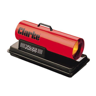
Clarke XR105 Посібник з експлуатації та обслуговування - Сторінка 8
Переглянути онлайн або завантажити pdf Посібник з експлуатації та обслуговування для Обігрівач Clarke XR105. Clarke XR105 8 сторінок. Paraffin/diesel heaters
Також для Clarke XR105: Інструкція з експлуатації та обслуговування (20 сторінок)

STARTING PROCEDURE
Warning!
Before starting the heater, you MUST ensure that the minimum ventilation
requirements are observed, to avoid the risk of carbon monoxide poisoning.
Ensure the fuel tank is filled with the correct fuel, before plugging in to a suitably
earthed supply. If you are changing the type of fuel, ensure the blanking plate at
the rear of the burner is set to the correct position (see Notes on page 7).
It will be necessary to remove the top cover, by removing its 6 securing screws, to
gain access to the rear of the burner, and the blanking plate.
If necessary, slacken off the blanking plate securing screw, turn the plate to its
required position and tighten the securing screw. Replace the top cover,
then,observing all precautions previously stated, push The start switch
located on the left side of the machine, and shown at 8, fig. 1.
It is important to ensure that adequate ventilation is provided. The following chart
gives the MINIMUM requirements
Minimum fresh air opening requirements
Minimum
Heater Model
Ventilation ft
XR75
XR105
XR155
eg. For XR75, a 3ft window must be open by 10" minimum
PARTS & SERVICE
Please contact your nearest dealer, or
CLARKE International, on one of the following numbers.
PARTS & SERVICE TEL: 020 8988 7400
PARTS & SERVICE FAX: 020 8558 3622
or
e-mail as follows:
PARTS: [email protected]
SERVICE:
Minimum
2
Ventilation mtrs
2
2.5
0.23
3.00
0.28
4.6
0.43
8
MAINTENANCE
Before carrying out any adjustment or maintenance, ensure the heater is
switched OFF, disconnected from the mains supply, and has been given
adequate time to cool down, unless otherwise stated.
It is essential that the heater is correctly maintained and kept in top condition at
all times.
Those items requiring regular maintenance comprise,
1.
Intake Air Filter (Item 2)
2.
Output Air Filter (Item 5)
3.
Fan (Item 20)
4.
Fuel Nozzle (Item 26)
- '1'
5.
Ignition Electrodes (Item 23)
6.
Fuel Filter (Integral part of item 27)
The Intake and Output Air Filters, are accessible by removing the Grille (by
removing the single hex socket centre screw), whereas accessibility to the
remaining items requires the removal of the top cover (by removing the six screws
at the centre joint).
Monthly
Intake Air Filter
Pull off the Intake Air Filter, which lies directly behind the Grille, and wash in a light
detergent. Thoroughly dry before re-installing.
In dusty environments it may be necessary to carry out this procedure weekly.
Never allow the filter to get blocked..
Ignition Electrodes
Having removed the heaters'
top cover, remove the single
screw retaining the electrode
holder. Withdraw the holder,
clean and adjust the gap
between the electrodes, to
4mm.
When re-installing the electrode holder, there must be a gap of 9mm between the
electrodes and the nozzle (see fig. 4). If this adjustment needs to be re-set, it is
preferable to remove the burner head complete, by removing the securing
screws around its' edge, taking care not to damage the photocell. The electrodes
may then be adjusted to their correct clearance before replacing the Burner
Head.
(ref. Parts List)
IMPORTANT
9
Fig. 4
