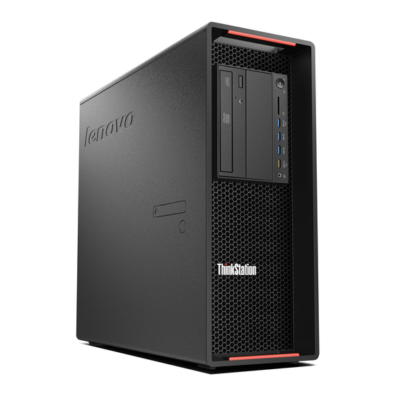
Lenovo ThinkStation P510 Конфігурація обладнання - Сторінка 16
Переглянути онлайн або завантажити pdf Конфігурація обладнання для Робочий стіл Lenovo ThinkStation P510. Lenovo ThinkStation P510 35 сторінок. How to create and
configure raid arrays
Також для Lenovo ThinkStation P510: Посібник з конфігурації (49 сторінок)

P900/P910
1.
Install the desired LSI controller to the appropriate slot in the system
a. For the LSI 9364-8i, the adapter must install to an available PCIe slot. Note that CPU2
must be populated for slot 6, slot 7, or slot 8 to be used. Refer to the system label for
slot locations.
-
Lift the card retention handle and remove the PCI blank for the slot to be
used.
-
Install the LSI 9364-8i into the PCIe slot.
-
Install the LSI ROC card air baffle on top of the LSI 9364-8i card.
-
Close the card retention handle.
b. For the LSI SAS/SATA FLEX RAID Adapter, the card must install to one of the FLEX
Connectors on the motherboard. Note that CPU2 must be populated for the (white)
FLEX Connector #2 to be used. Refer to the system label for FLEX Connector locations.
-
Lift the card guide tab near the FLEX Connector
-
Install the FLEX Adapter into the slot making sure the card guide is engaged on
the right side of the card.
-
Close the card guide tab to secure the adapter.
2. Locate the mini-SAS HD cable (labeled S/X) from the lower BCA-S (bays 1 and 2) and attach it to
the connector on the LSI controller. For LSI 9364-8i, connect the S/X cable to Port 0 (right) on
the card. For the LSI SAS/SATA FLEX RAID Adapter, connect the S/X cable to P1 on the FLEX
Adapter.
3. Locate the mini-SAS HD cable (labeled S/X) from the upper BCA-S (bays 3 and 4) and attach it to
the connector on the LSI controller. For LSI 9364-8i, connect the S/X cable to Port 1 (left) on the
card. For the LSI SAS/SATA FLEX RAID Adapter, connect the S/X cable to P2 on the FLEX Adapter.
4. Once AC power is applied to the system, the BCA(s) should now illuminate LEDs to indicate
which ports are active as well as which drive types (SATA and SAS) are supported.
5. Install all drives to the FLEX Trays. Note that with LSI controllers, each FLEX Tray can support up
to two drives (one 3.5" drive and one 2.5" drive per tray; certain physical limitations apply).
6. Insert the populated FLEX Tray(s) fully into the bay, and push the pull-bar feature such that it is
flush with the bay.
