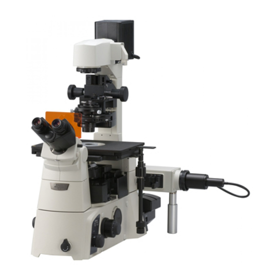
Nikon eclipse Ti-U/B Інструкція з експлуатації - Сторінка 24
Переглянути онлайн або завантажити pdf Інструкція з експлуатації для Мікроскоп Nikon eclipse Ti-U/B. Nikon eclipse Ti-U/B 25 сторінок. Inverted microscope

1.7
Power Supply
1.7.1
TI-PS100W Power Supply
Warning
The bottom of the power supply device becomes hot during use. Do not block the air vents on
the side of the product.
POWER indicator
Brightness
control knob
POWER switch
POWER switch
This is the power switch for the power supply. Press
the "I" side of the switch to turn on the power supply
and output DC power from the 12VDC output on the
rear. Press the "O" side of the switch to turn off the
power supply.
POWER indicator
Lit when the power supply is on.
Brightness control knob
When the EXTERNAL switch is turned off, the knob
controls the brightness of the lamp by adjusting the
voltage supplied from the 12VDC output connector.
AC inlet
This is the connector for connecting the power
supply device to a wall outlet. Be sure to use the
specified power cord for the connection.
EXTERNAL (external control) ON/OFF switch
Turn this switch on to use the brightness control
knob on the microscope for output voltage control.
When this switch is turned off, the brightness control
knob on the front of the power supply becomes
enabled, and the brightness control knob on the
microscope becomes disabled.
Chapter 1 Part Names
1.7 Power Supply
AC inlet
Figure 1-22 TI-PS100W Power Supply
EXTERNAL (external control signal input)
connector
Connect the control cable to this
connector and the LAMP CTRL
connector on the rear of the
microscope.
Pin Signal
1
2
3
4
5
6
7
8
12VDC output connector
This connector supplies power to the 12V 100W
halogen lamp. Connect the lamp cable for the pillar
illuminator.
22
EXTERNAL ON/OFF switch
External resistor terminal for output voltage adjustment
External resistor terminal for output voltage adjustment
Output voltage ON/OFF switch (input)
GND (0V)
External voltage input for output voltage adjustment
EXTERNAL switch on/off detect signal (output)
GND (0V)
Output voltage monitor terminal (output)
Connector: HR12-10R-8SC by Hirose Electric Co., Ltd.
2
1
3
Connector: SRCN2A13-3S by Japan Aviation Electronics Industry, Ltd.
12VDC output
connector
EXTERNAL connector
1
2
3
4
5
6
7
8
Pin
Signal
1
Output +
2
Output -
3
Not used
