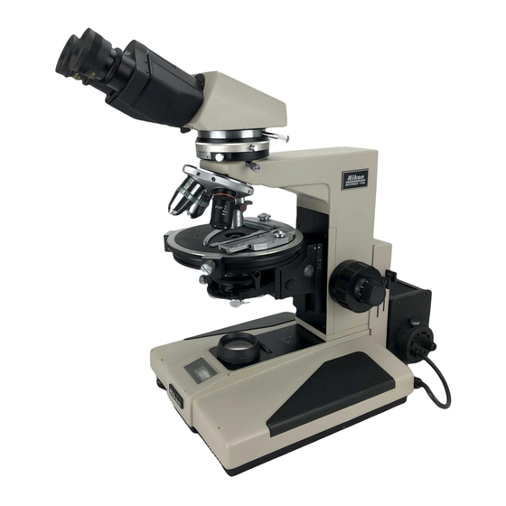
Nikon OPTIPHOT-POL Інструкція з експлуатації - Сторінка 14
Переглянути онлайн або завантажити pdf Інструкція з експлуатації для Мікроскоп Nikon OPTIPHOT-POL. Nikon OPTIPHOT-POL 28 сторінок. Polarizing microscope

might fail to focus its image on the speci-
men.
8)
Bertrand lens
(with the trinocular
eyepiece tube "TP" or
the binocular eyepiece tube "BP" in use)
•
Bring the Bertrand
lens into the optical
path
by turning
the Bertrand
lens ring
leftward to observe the conoscopic image.
(Fig. 20)
In the above simultaneous
observation
of
the
conoscopic
and orthoscopic
images,
the
former
image may appear deviated
from
the orthoscopic
view field
center,
however,
the
deviated
image represents
the conoscopic
light flux that covers the
central part of the orthoscopic
view field
to the extent of about 1/18.
9)
1/4
'A
& tint plate
•
Removing the 1/4 'A plate side screw, hold
the
1/4 'A & tint
plate,
the cI ick stop
groove facing the operator
and insert it
forward into the compensator slot.
Then screw-in the above screw as it was.
(Fig.23)
Fig. 23
•
The tint
plate has an empty
hole at the
center. By pushing it through the slot, the
sensitive
tint
plate
(530nm)
is brought
into the optical path and by pu IIing it out
the 1/4 'A p late is brought into the optical
path.
10) Dia-polarizer and analyzer
•
When the both are set at ~ read ing on the
protractor
scale, position
of the polariza-
tion
plane coincides with the orientation
plate, which shows that the indication
"P"
of the X-direction
is for dia-polarizer
and
the
"A"
of the V-direction
is for analyzer,
on the microscope base. (Fig. 24)
[Note] Some
of
the
polarizing
micro-
scope's reference books or special
works available in the market may
explain
that the X-direction
is for
analyzer
and the V-direction,
for
polarizer.
Conoscopic image
of this area can be
observed
--Orthoscopic
viewfield
•
The conoscopic
view field
is as large as
about 1/4 of the orthoscopic
view field.
(Fig. 21)
Bertrand lens
ring
Fig. 20
Fig. 21
•
The conoscopic
image may also be observ-
ed overlapping
on the orthoscopic
image
through
the binocular
observation, one of
the paired eyepieces being replaced with
the accessory pin hole eyepiece and with-
out the Bertrand
lens in the optical path.
(Fig.22)
Fig. 22
