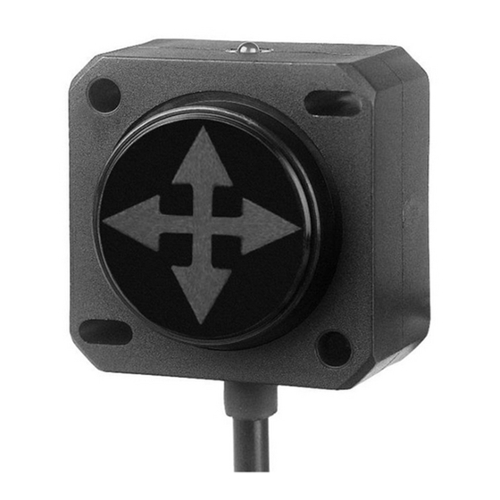
DIS Sensors QG40N Посібник користувача - Сторінка 6
Переглянути онлайн або завантажити pdf Посібник користувача для Перемикач DIS Sensors QG40N. DIS Sensors QG40N 15 сторінок. Tilt/acceleration switch (sil1 plc)
Також для DIS Sensors QG40N: Посібник користувача (5 сторінок), Посібник з експлуатації та техніки безпеки (6 сторінок)

4 Functional Description
Safety Switch Explained
The safety function of the switch sensor is to generate the requested switching behaviour based on
inclination or acceleration values (caused by gravitation) measured by a MEMS acceleration sensor
chip. Based on this switching behaviour (one non-conducting output = unsafe) the safety controller of
the application can switch the machine to safe-mode in order to prevent for a dangerous situation.
Example:
A crane-arm is designed with a maximum tilt angle concerning the chassis. When the crane arm
exceeds a critical tilt angle, it can pose a safety risk. To prevent this, a Tilt switch can be mounted on
the crane arm to measure its angle. The safety controller of the application is responsible for
monitoring the Tilt switch outputs. If any of the outputs become non-conductive, the safety
controller activates the crane's safe mode promptly. This proactive measure significantly minimizes
the risk of hazardous situations.
The Safety Related Fault Response Time (SRFRT) of this device is defined as the maximum time
the sensor will report a non-safe situation to the outside world, after detecting an internal safety
error. The actual value is specified in the datasheet
4.1.1
Tilt Switch
A tilt switch is a sensor that triggers a change in output (e.g., NPN/PNP signals) based on the changes
in angle of tilt or inclination beyond a predefined threshold, typically measured in relation to Earth's
gravity..
The device takes both the static component (100%) and the dynamic component (partial, depending
on frequency and bandwidth-setting) into account.
4.1.2
Acceleration Switch
An acceleration switch is a sensor that triggers a change in output (e.g., NPN/PNP signals) based on
the changes in acceleration beyond a predefined threshold, indicating a specific acceleration event or
condition. An Acceleration sensor measures the acceleration in 1, 2 or 3 axes.
Internally the sensor has a 'measuring interval' depending on the measuring mode:
PEAK (default): The peak acceleration value is calculated over the fixed 40ms measuring
•
interval.
•
RMS (optional): The RMS acceleration value is calculated over a factory programmable
measuring interval of n*40ms, where n=integer, with a max. of 10 seconds.
DIS SENSORS BV
User Manual - QG40N Tilt/Acceleration Switch (SIL1 PLc) V2.0
5
