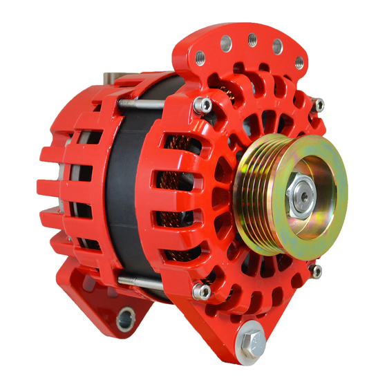
Balmar 97EHD Series Посібник з монтажу та експлуатації - Сторінка 9
Переглянути онлайн або завантажити pdf Посібник з монтажу та експлуатації для Портативний генератор Balmar 97EHD Series. Balmar 97EHD Series 20 сторінок. Alternator

USING THE SMARTREADY
®
INTERNAL VOLTAGE
REGULATOR
The 6-Series and XT-Series alternators
are unique among Balmar alternators, in
the fact that it is equipped with a single
stage Smart Ready
internal regulator.
®
Designed to be used as a stand-alone
or emergency spare, the Smart Ready
®
regulator can be wired, as shown at right,
to take over in the case of an external
regulator failure.
By installing a double throw toggle switch
from a switched source of voltage the
user can quickly switch from one regula-
tor to the other by shutting down the en-
gine, flipping the switch and restarting the
engine.
NOTE: The alternators can only be con-
trolled by one voltage regulator at a time.
DO NOT connect the internal regulator's
(BROWN) excite wire and the external regulator's (BROWN) excite wire to ignition voltage at the same time. Doing
so could result in an over voltage condition that could harm the alternator, regulators and batteries being charged.
WARNING
The engine MUST be turned off prior to switching between external and internal regulators.
Failure to do so will result in damage to the internal regulator.
USING THE SMART READY
REGULATOR WITH A BATTERY ISOLATOR
®
The Smart Ready
internal regulator requires power at the alternator's positive output to properly regulate charging
®
voltage. In systems where charging output is directed to multiple battery banks by a diode-based battery isolator,
the alternator's positive output is isolated from battery voltage by the diodes.
The following diagram illustrates the use of a 3-amp, 200-volt axial diode to bleed a small amount of current to the
positive output post when the internal regulator is activated. Note that the internal regulator's (RED) sense wire
must be connected to the isolator output post that supplies the primary (house) battery bank. The axial diode is
spliced into the (BROWN) ignition wire and is connected to the alternator's positive output post. Ensure that the
axial diode output (indicated by bar on the diode, is connected closest to the alternator's positive output post.
Page
9
