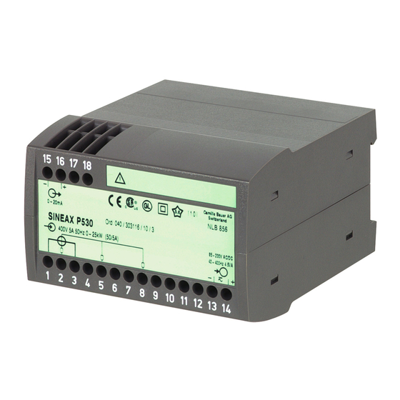
Camille Bauer Sineax p 530 Інструкція з експлуатації - Сторінка 18
Переглянути онлайн або завантажити pdf Інструкція з експлуатації для Перетворювач Camille Bauer Sineax p 530. Camille Bauer Sineax p 530 20 сторінок. Transducer for active or reactive power

Output
Test and
Output signal
conformity marks
15
16
17 18
–
+
–20...20mA
Ord: 123 / 123456 / 123 / 123
SINEAX P530
133.33V 5A 50Hz –2000...2000kW (440kV/133.33V 2500A/5A)
1
2
3
4
5
6
7
8
Measuring Input
Input voltage
Input current
Nominal frequency
Measuring range
Measured quantity
The figures in brackets are the
ratios of the main v.t's and c.t's
Fig. 5. Declaration to type label.
6. Adjustable measuring range by
DC calibration
A DC-calibration with the following types is impossible:
Type 531 – 41.. for reactive power 3-wire 3-phase
balanced load
Type 531 – 43.. for reactive power 4-wire 3-phase
unbalanced load
The measurement inputs must be effectively
separated from dangerous voltage!
DC calibration is performed at the user's
risk. The warranty is void as soon as the
calibration seal is removed.
– Remove the calibration seal (small sticker, Fig. 5).
– Connect the power supply
from the measurement input to terminals 2 and 5).
– Instruments with current output ...
... connect a mean output load (0.5 · R
instrument (e.g. MetraHit 18s) to the output
Example: Output 0...10 mA, load voltage ± 15 V
External resistance R
connect a mean
output load of 0.75 kΩ
18
Calibration seal
Camille Bauer AG
5,6
0,5
Switzerland
Works No.
85 - 230V AC/DC
40 - 400Hz 4.5VA
–
+
9
10
11
12
13
14
Power supply
(if this has to be wired
max.) and an
ext
15 V
max. =
= 1.5 kΩ
10 mA
ext
– Instruments with voltage output ...
... connect an output load (2 · R
(e.g. MetraHit 18s) to the output
Example: Output 0...10 V, load capacity 4 mA
Ext. resistance R
connect an
output load of 5 kΩ
– Zero the output (i.e. zero output corresponds to zero input
current).
– Calculate the calibration factor c:
Full-scale of measuring range
c =
Apparent power
The apparent power for single-phase AC = U · I
The apparent power for three-phase AC = U · I ·
Take note of the permissible calibration factor,
for active power ≥ 0.75 to 1.3 ·
for reactive power ≥ 0.5 to 1.0 ·
If the input is connected via an instrument transformer,
primary values must be inserted for U, I and the full-scale
value of the measuring range.
– Calculate the DC calibration voltage Ucal:
U
N
Ucal =
U
U
N
·
Ucal =
U
If the effective nominal input voltage U
following standard ranges, insert U = U
The standard nominal voltage ranges are as follows:
Standard nominal ranges
1) 100 ... 115 V
2) 200 ... 230 V
2) 380 ... 440 V
4) 600 ... 690 V
Should the effective nominal input voltage U
one of the standard ranges listed (non-standard [V] > 115.00
and < 600;) insert the effective nominal voltage U
Non-standard nominal
input voltages
> 115.00 to < 600 V
– Connect the DC calibration voltage to X174 (–) and X173
(+) (e.g using MetraHit 18c).
– Calibrate the full-scale of the output on P171.
– Check the output zero and calibrate if necessary on
.
P231.
– Check the full-scale of the output and calibrate as neces-
sary (repeat until full-scale and zero are correct).
– Recover calibration hole.
min.) and an instrument
ext
min. =
4 mA
ext
3
· U · I
3
· U · I
· c
active power
c
reactive power
0,7
is within one of the
N
N min
U = U
100 V
200 V
380 V
600 V
U = U
e.g. 500 V
.
10 V
= 2.5 kΩ
3
!
N min
not be within
N
!
N
N
