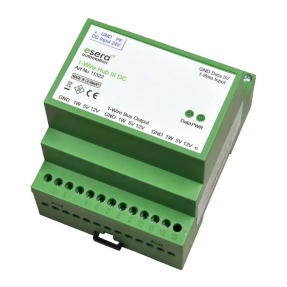
esera automation 1-Wire Hub III DC Посібник користувача - Сторінка 2
Переглянути онлайн або завантажити pdf Посібник користувача для Блок управління esera automation 1-Wire Hub III DC. esera automation 1-Wire Hub III DC 6 сторінок. Auto-e-connect

3
Auto-E-Connect® Support
The ESERA Auto-E-Connect® 1-Wire Plug and Play system will be used for the
1-Wire Bus supported. This enables fully automatic configurations of 1-Wire sensors
and actuators on the 1-Wire bus. It is optimized for industrial applications and
enables significant added value beyond the sensor and chip data.
The Auto-E-Connect function automatically recognizes ESERA chips, sensors and actuators, starts suitable
libraries and outputs fully formatted data.
The Auto-E-Connect functionality will be available from mid-2020 via 1-Wire Controllers, 1-Wire Gateways and
1-Wire ECO from ESERA available.
Further information on ESERA Auto-E-Connect can be found on the ESERA website, ESERA Config-Tool 3, or in
the download area for this article in the ESERA Webshop.
4
Technical data
1-Wire function:
Port function:
Input voltage:
Energy Efficiency:
Output Power:
Output:
Indicator:
Interfaces:
Function:
Connection:
Auto-E-Connect:
5
Ambient conditions
Protection system:
Protection class:
Temperature, operation: -10°C to +50°C
Air humidity:
Dimensions:
Weight:
6
Conformity
EN 50090-2-2
EN 61000-4-2, ESD
EN 61000-4-3, HF
EN 61000-4-4, Burst
EN 61000-4-5, Surge
EN 61000-6-1, Fault-free operation
EN 61000-6-3, Stray radiation
RoHS
7
LED indicators
The module has different display LED`s. Please refer to the following table for their functions:
LED status
LED green
LED green
All rights reserved. Reproduction as well as electronic duplication of this user guide, complete or in part, requires the written consent of
ESERA GmbH. Errors and technical modification subject to change. ESERA GmbH, ESERA-Automation 2020
www.esera.de
DS2450 commands, current and voltage output measurement
Port 0 = current 12 V
Port 1 = voltage 12V
Port 2 = current 5V
Port 3 = voltage 5V
typ. 24 V DC (18 – 36 V DC)
>= 90 %
max. 15W
5 V maximum 0,5 A
12 V maximum 1 A (in total for 5 V and 12 V maximum 15W)
Power LED (5 V) and 1-Wire activity
Input for 1-Wire Controller or 1-Wire Bus Coupler
Output for 3 x 1-Wire network (output 1 adjacent top-hat rail modules)
The devices has no repeater function for 1-Wire data lines
Outputs are connected internally.
Screw terminals up to 2.5 qmm cable cross section
will be supported
IP20
III
10 - 92% (non condensing)
71 x 71 x 90 mm (WxHxD)
174 g
Description
Function
Power
Display for 5 V output voltage (if LED is lit, 12 V output voltage is
available due to the system)
Data
11322 V2.0 R1.1 Manual
(12 Bit, 5 V)
(12 Bit, 5 V)
(12 Bit, 5 V)
(12 Bit, 5 V)
Flashes at 1-Wire activity
Is permanently lit if 1-Wire Bus Coupler is missing or input is
not connected
Is permanently lit in case of a short circuit of one of the 1-
Wire outputs
Page 2 of 6
