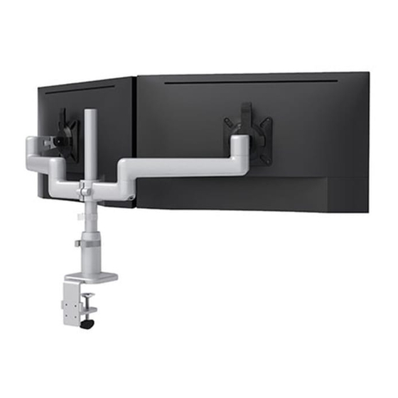
ESI KATAEX2-GM-FMS-BLK Інструкція з монтажу Посібник з монтажу - Сторінка 7
Переглянути онлайн або завантажити pdf Інструкція з монтажу Посібник з монтажу для Стелажі та підставки ESI KATAEX2-GM-FMS-BLK. ESI KATAEX2-GM-FMS-BLK 12 сторінок. Dual fixed+motion+slider monitor arm

KataEX2-FMS
Step #8: remove cable management covers
• To remove the cover from the motion arms, slide the cable cover
upward.
• To remove the cover from the fixed arms and arm stems, slide the
cable cover out.
Step #9: install lockout set screws, if desired
Default rotation of the fixed arms and motion arms is 360°. Installation of a lockout set screw limits rotation to 180°.
• To lockout rotation of the fixed or motion arms, install an M4x15 set screw in the underside of the arm stem. Tighten the screw, then back it off one turn.
— Installing a set screw in the front hole allows 180° rotation to the right only. A set screw in the rear hole allows 180° rotation to the left only.
— In the example below, to prevent the fixed arms from rotating to the rear (a left rotation with the left arm and a right rotation with the right arm),
install a set screw in the front hole on the left arm stem and the rear hole on the right. The motion arms are allowed their full 360° of rotation.
• The fixed arm or motion arm must be in its allowed range of rotation when installing the lockout set screw.
monitors
not shown
front
set screw
M4x15
rear
2mm
Allen key
360°
180°
slide up
180°
Page 7
Assembly
motion arm
fixed arm
arm stem
slide out
slide out
360°
front
rear
