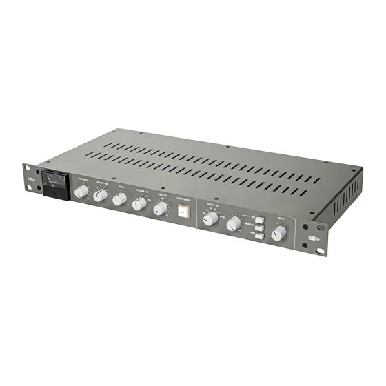
DIYRE G BUS Посібник з експлуатації - Сторінка 6
Переглянути онлайн або завантажити pdf Посібник з експлуатації для Повітряний компресор DIYRE G BUS. DIYRE G BUS 13 сторінок. Stereo vca compressor

Block Diagram
Audio enters the G Bus through the input amplifier, which converts the signal from balanced to unbalanced. It
then splits to three places: the mix circuit, the rest of the audio path, and the sidechain (SC).
In the mix circuit, the output from the balanced input is summed with the output from the audio VCA. The
following
MIX
switch selects between the output from the VCA (default) and the output of the mix circuit.
In the audio circuit, the signal passes through the unity gain trim and into the audio VCA, which controls the level
based on the control voltage (CV) from the SC. It then goes to the mix circuit and switch.
In the sidechain, the signal passes through the
MONO SC
switch, where it is either summed to mono or left stereo.
It then passes through the filters and into the SC VCA. This VCA acts as a mirror of the audio VCA, essentially
creating feedback behavior where the sidechain "sees" the signal after it is compressed. The signal is then
converted to DC and manipulated by the ratio, attack, and release sections. The signal that emerges is the CV. It is
sent to three places: the meter, the SC VCA (feedback), and the audio VCA's control port. The
THRESHOLD
control
sets the sensitivity of the compressor by controlling the gain of the SC VCA. The
MAKE-UP
control provides extra
gain at the audio VCA.
Returning to the audio path after the
MIX
switch, the signal goes to the IC (default) and XFMR outputs in parallel.
The
XFMR
switch selects which output will go to the balanced output jacks.
4
