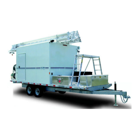
Aluma Tower Company TM52WA60-EB4S7 Інструкція з експлуатації - Сторінка 7
Переглянути онлайн або завантажити pdf Інструкція з експлуатації для Утилітарний транспортний засіб Aluma Tower Company TM52WA60-EB4S7. Aluma Tower Company TM52WA60-EB4S7 12 сторінок. Tower setup with guy wires includes guying to outriggers

2.
Using the manual brake winch on the rear support, crank the tower from the
horizontal to the vertical position. At the halfway position undo the nut(s) from
the latch bolt(s) at the bottom rear of the trailer frame (see Fig. 7).
NOTE: Sufficient load must be applied to the cable to overcome internal
resistance and operate brake properly. NEVER CONTINUE TURNING THE
HANDLE COUNTER-CLOCKWISE IF THE CABLE DOES NOT KEEP
MOVING OUT. This will disengage the brake mechanism and create an unsafe or
hazardous condition.
MINIMUM OPERATING LOAD REQUIREMENTS - MODEL 5351 - 75 lbs.
Failure to read and apply the instructions and warnings contained in this manual
can result in sudden failure of equipment, property damage and serious injury.
3.
Secure the tower in the vertical position with the tower lockdown bar pivoting
over the latch bolt(s) on bottom of rear trailer frame (see Fig. 7). Tighten the
nut(s) with wrenches supplied in tool kit, TM-TK which is stored in the #664 or
#684 storage box. Drive all three "Duckbill Ground Anchors" into the ground as
described in the attached instructions, AT-418-1.
4.
Take the loose end of the three lowest guy wires and attach them to the ground
anchors. Tighten only the lowest set of guy wires. The turnbuckles should be
adjusted to the fully extended position for maximum adjustment. Recheck the
bubble levels to be sure the trailer is still level. Also use the 4-foot level to further
check to see that the tower is as level and plumb as possible. If tower is not level,
readjust the jacks on the trailer to re-level trailer.
5.
IMPORTANT: Undo the Red Safety strap from the bottom of the tower and
remove it from the inner sections. It is necessary for this strap to be removed.
The power winch raising the tower is capable of damaging the tower if this strap
is not removed. Please note that this strap is used to keep the tower from
telescoping out on its own when in the transport mode. Additionally, you should
pull the orange safety stop release cord to insure the safety stop releases properly
before raising the tower.
CAUTION ! Do not attempt to raise tower in winds over 10 mph. Even in winds
between calm and 10 mph there MUST BE a person at each of the Guy Wires to
insure that the WIRES are kept taut.
6.
Raise the tower to the desired height. The safety stop engages at a rung
approximately every 20 inches. Remember that the electric winch is capable of
damaging the tower, so be alert to any unusual noises or signs that may indicate
that you are doing damage to the tower. Do not try to overextend the tower.
The tower is fully extended when the black and orange tape bands on the vertical
legs of the outer section are aligned with the bands on the inner section. When at
maximum height, the rung marked with orange reflective tape is just above the
safety stop mechanism, allowing the safety stop to rotate under this rung. The
safety stop is located at the top of the lowest section. Allow the tower to lower
until the inner section rung, marked with orange reflective tape, rests on the safety
stop. Winch cable will slacken when this occurs. Serious damage will occur if
overextended!
2/13/2012
Page 6
TRAILER TOWER SETUP INSTRUCTIONS-GUYED TO OUTRIGGERS
