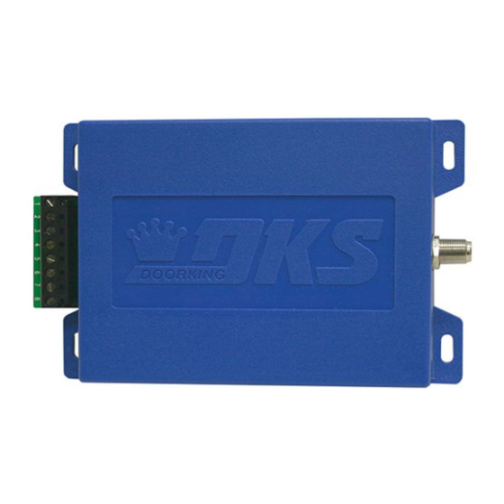
DKS 8040 microplus Посібник користувача - Сторінка 3
Переглянути онлайн або завантажити pdf Посібник користувача для Приймач DKS 8040 microplus. DKS 8040 microplus 3 сторінки. Rf receiver (weigand)
Також для DKS 8040 microplus: Посібник користувача (4 сторінок)

Match or Ignore Facility Code
The receiver can be programmed to MATCH or IGNORE the Learned transmitter's facility code.
1A. Turn the Programming Selector to "Position 5" will MATCH the Learned transmitter's facility code.
1B. Turn the Programming Selector to "Position 6" will IGNORE the Learned transmitter's facility code (Factory Setting).
2. Press and hold Program Button until the Program LED flashes ONCE and receiver will BEEP once.
3. Receiver LED will then give a long flash and beep.
4. This indicates receiver is now changed to "Your Selection in Step 1".
NORMAL -Power Mode (Factory Set)
The receiver comes from the factory already set in NORMAL-Power mode. It can be changed from LOW-Power back to NORMAL-Power mode.
1. Turn the Programming Selector to Position 9.
2. Press and hold Program Button until the Program LED flashes ONCE and receiver will BEEP once.
3. Receiver LED will then give a long flash and beep.
4. This indicates receiver will be put into NORMAL-Power mode which consumes MORE power than LOW-Power mode.
Change to LOW -Power Mode
The receiver can be changed from normal-power to LOW-Power mode. LOW-power mode is used in DoorKing solar gate operator applications.
Wiegand output will NOT work in LOW-Power mode.
1. Turn the Programming Selector to Position 8.
2. Press and hold Program Button until the Program LED flashes ONCE and receiver will BEEP once.
3. Receiver LED will then give a long flash and beep.
4. This indicates receiver will be put into LOW-Power mode which consumes LESS power than NORMAL-Power mode.
Erase ALL Memory - This CANNOT be UNDONE
1. Turn the Programming Selector to Position A.
2. Press and hold Program Button until the Program LED flashes ONCE and receiver will BEEP once. Press and hold button again, LED will flash
and receiver will beep again. Press and hold button a third time, LED will flash and receiver will beep a third time.
3. The receiver will then emit a long flash and long beep indicating ALL memory, including master transmitters have been erased from memory.
Note: If receiver does not emit a continuous beep after pressing the button 3 times, try repeating step 2 faster or slower until it does.
STAND-ALONE RECEIVER SETUP - RELAY CONNECTION
The receiver contains a built-in relay that can operate an access device such as a gate operator or door lock. Connect receiver terminals #3 and #5
to a normally open access device or terminals #4 and #5 to a normally closed access device. The memory of the receiver can ONLY store 100
MicroPLUS or MicroCLIK transmitters MAXIMUM. The relay will activate when the correct Facility Code and Transmitter Button Code match the
codes that have been stored in the memory from a single transmitter (Learned).
Programming Selector's 8 positions that can be used:
1. Learn Transmitters (See below)
5. Match Facility Code
6. Ignore Facility Code (Factory Setting)
8. Low-Power Mode (Stand-Alone Setup ONLY)
9. Normal-Power Mode (Factory Setting)
A. Erase ALL Memory
B. Set Receiver to MicroPLUS Mode (Factory Setting)
C. Set Receiver to MicroCLIK Mode
Learn Up to 100 Transmitters
1. Turn the Programming Selector to Position 1.
2. Press and HOLD Program Button until the Program LED flashes ONCE and
receiver will BEEP once. Receiver is now in "Learn Mode" and will flash and
beep every second for 10 seconds.
3. Press a specific button on the desired transmitter to be "Learned" within
10 seconds. Receiver will reset 10 second timer after each transmitter button
has been pressed.
4. Press other desired transmitter buttons to be learned, each within 10 seconds.
5. After all desired transmitters have been learned by the receiver, wait 10
seconds for the receiver to time-out and end programming.
8040 065-E-7-14
Access Device Relay
Connection
R e
T e r
#1 - Input Power Common
#2 - Input Power
#3 - Relay N.O. Normally Open
#4 - Relay N.C. Normally Closed
#5 - Relay Common
#6 - Wiegand Common
#7 - Wiegand Data 0
#8 - Wiegand Data 1
3
n e c
o n
F C
c e i
v e r
m i
antenna, coax
n a
l
n
t t o
B u
connector are
r a m
r o g
D P
L E
isolated from
m
g r a
P r o
(Negative)
12-24 Volt AC, 12-24 Volt DC (Positive)
DO NOT Use.
18"
t o r
Coax
Cable
Be sure the
Coax
Antenna
shield and F
Kit
(Included)
completely
the ground.
