Clippard EVPD Посібник з монтажу та експлуатації
Переглянути онлайн або завантажити pdf Посібник з монтажу та експлуатації для Приводи постійного струму Clippard EVPD. Clippard EVPD 3 сторінки. Proportional valve driver
Section 1 Wiring
Step 1:
Configure Jumper 1 Based on Command
Command
Type
J1
Jumper
Configuration
* Factory Jumper setting. PWM voltage must correspond to
Jumper selected voltage.
Δ
Caution: Do not exceed Command Input Range by more than
25% or permanent damage may occur to the driver.
Step 2:
Configure Jumper 2 Based on Valve
DVP/EVP
DVP/EVP
J2 Jumper
J2 Jumper
Valve Type
Valve Type
Configuration
Configuration
0 to 5 VDC
0 to 5 VDC
0 to 10 VDC
0 to 10 VDC
0 to 20 VDC**
0 to 20 VDC**
* As per DVP or EVP specifications
Step 3:
Connect Valve to Valve + and Valve -
Terminals
(Valve is not polarity sensitive.)
Step 5:
Connect Power to +VDC and GND Terminals.
voltage specification. The table below shows the recommended input voltage range for each valve type.
DVP/EVP
Drive Supply
Valve Type
Voltage Range
0 to 5 VDC
7 to 12 VDC
0 to 10 VDC
12 to 28 VDC
0 to 20 VDC
24 to 28 VDC
WARNING: Installation and operation of electronic and high pressure systems (fluids and
compressed gas) involves risk including property damage and personal injury or death.
Users should be properly trained or certified and take safety precautions.
0 to 5 VDC or
0 to 20 mA or
0 to 10 VDC*
4 to 20 mA
Board
Board
Valve Max.
Valve Max.
Output
Output
Current*
Current*
400 mA
400 mA
370 mA
370 mA
200 mA
200 mA
185 mA
185 mA
100 mA**
100 mA**
92 mA
92 mA
** Factory Jumper setting
Clippard DVP or
EVP Series Valve
Ideal Supply
Voltage
12 VDC
24 VDC
28 VDC
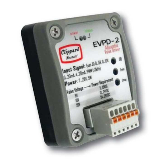
EVPD PROPORTIONAL VALVE DRIVER
Installation & Operations Manual
Power
1.56"
(39.6 mm)
1.31"
(33.3 mm)
Power (See Step 5)
Common (GND)
Valve +
Valve -
Voltage Command
Current Command
Step 4:
Connect Command Source
Current Command Type
Unused command input should be grounded to
ensure proper operation of the driver. For PWM command,
use voltage command terminal.
Power requirements are determined by valve
Upon successful powering of the board, the Power
LED (red) will become lit.
CLIPPARD INSTRUMENT LABORATORY, INC. • ISO 9001:2015
1.26" (32 mm)
1.00" (25.4 mm)
St
Status Indicator
St
tatu
LED
LED
D
LED
0.104"
dia.
Command
Threshold (DB)
Current Min. (Imin)
Current Max. (Imax)
Jumper 1 (J1)
10V
Jumper 2 (J2)
EVPD Output
0 to 100 mA
0 to 200 mA
0 to 400 mA
Wiring Configuration
Voltage Command Type
Power LED
877-245-6247 |
5V
Valve
370 mA
185 mA
92 mA
clippard.com