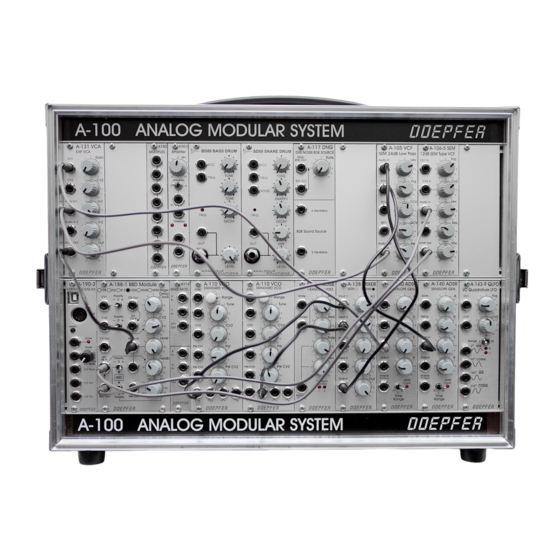
Installing modules
•
To be on the safe side please calculate the total current requirement of existing modules plus the
new module/s.
•
Check that this total is less than the current that is provided by the supply (in case of A-
100G6/P6/P9/LC6/LC9/LCB) or the supplies (for monster cases).
•
Normally this will apply, provided that only A-100 modules are used.
•
If that's OK: First of all, take the A-100's plug out of the wall socket.
•
Check if each module is equipped with a ribbon cable with a 16 pin female connector at the open
end. The ribbon cable can be 10 or 16 pin but the female connector has to be 16 pin !
•
Now join the free end of the ribbon cable to the nearest available position on the system bus board
•
For this one has to plug the female 16 pin connector at the free end of the ribbon cable to one of
the pin headers of the bus (these are also 16 pins). Use a pin header of the bus board that is close
to the position where the module has to be mounted later.
•
Check very carefully that it is connected so that the coloured marking on the ribbon cable is at the
bottom of the bus connector. The coloured marking has to align with the "-12V" printing on the
bus board next to the pin header.
•
Check also very carefully that it is pushed fully home, not at a slight angle and not vertically or
horizontally displaced .
•
Failure to check this may result in the module's instant destruction as soon as the power is turned
back on! Even the power supply may be damaged or the fuse may blow.
•
When you're installing extra modules, it may be necessary to take another module or two out, to
allow you easier access to the bus board.
•
Place the module carefully into the space in the rack, and fasten it firmly in place with the supplied
screws (M3x6).
•
Repeat this procedure until all modules (and possibly blind panels) are installed and the front of the
A-100 case is fully closed.
•
Now plug the system A-100 back into the main power supply, and switch it on.
•
Test out the newly installed modules.
•
If it doesn't seem to be working as expected, immediately disconnect the system from the power
supply again.
•
In this case, double-check all connections, making completely sure that the ribbon cables are the
right way round where they connect to the bus.
Interconnecting modules
For connecting modules to each other, you need mono mini-jack (3.5 mm) patch leads. We offer
patch leads in different lengths (from 15 cm to 2 m) and colors.
6

