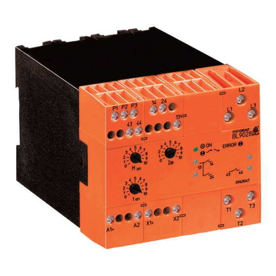
DOLD MINISTART BL 9028 Переклад оригінальної інструкції
Переглянути онлайн або завантажити pdf Переклад оригінальної інструкції для Контролер DOLD MINISTART BL 9028. DOLD MINISTART BL 9028 6 сторінок. Softstarter with braking function

Power Electronics
MINISTART
Softstarter with braking function
BL 9028
Product Description
Softstarters are electronic devices designed to enable 1-phase or 3-phase
induction motors to start smoothly. By means of internal current monitoring
we realise different protective functions, when stalling the motor or during
heavy duty starting. The semiconductors are bridged after softstart by relay
contacts. This reduces power dissipation and heating. The device parameters
are adjusted using potentiometers. LEDs indicate the status of the device.
Function diagram
L1/L2/L3
A1/A2
X1(+)
/ X2
13-14
13-24
43-44
T1
T2/T3
M Mot
n
t 0
t 1
t 2
t 0
: start
t 4
: stillstand detection
t 0 -t 1 : brake function test
t 1 -t 2 : ramp up time
t 3 -t 4 : braking time
All technical data in this list relate to the state at the moment of edition. We reserve the right
for technical improvements and changes at any time.
t
t 3
t 4
t 0
t 1
M10208_b
Translation
of the original instructions
• According to IEC/EN 60947-4-2
• 2-phase motor control
• For motors up to 11 kW at 3 AC 400 V
• Separate settings for start and brake time, as well as
starting and braking torque
• No braking contactor necessary
• Function test of brake circuit before softstart
• With automatic standstill detection
• Current monitoring
- to protect the power semiconductors
- for device protection at stalled motor
• Maintenance- and wearfree
• Auxiliary DC 24 V
• Monitors undervoltage and phase sequence
• With input to detect motor temperature via PTC (variant /_1_)
• 3 relay outputs for indicaiton of status and fault with LED-indication
• Width: 112.5 mm
Approvals and Marking
Applications
• Motor with gear, belt or chain drive
• Fans, pumps, conveyor systems, compressors
• Woodworking machines, centrifuges
• Packing machines, door-drives
Function
The devices slowly ramps up the current on two phases, therefore allowing
the motor torque to build up slowly. This reduces the mechanical stress on
the machine and prevents damage to conveyed material.
Start/Stop switch
When the motor is on full speed after the starting with start/stop switch
S the semiconductors are bridged with internal relay contacts to prevent
internal power losses and heat built up. When stopping the motor via start/
stop switch S braking is started.
The braking current flows until the motor standstill is detected but not longer
(max. 20 s) through the motor windings.
Monitoring relay 1 (contact 13-14)
The relay energizes at the end of the softstart ramp and de-energizes at the
beginning of the braking cycle. (operation with bridged semiconductors).
When a failure occurs the relay de-energizes when the semiconductors
switch off.
Monitoring relay 2 (contact 13-24)
This relay energises as soon as the unit is ready for operation after connecting
it to power. If any error occurs the monitoring relay 2 will be de-energized
immediately. The power output will be switched off.
Monitoring relay 4 (contact 43-44)
This relay is energized when motor standstill is detected. It will be reset
by starting the
motor.
The monitoring relay 4 is de-energized if an error
occurs.
Input P1/P2/P3 to monitor the motor temperature (variant /_1_)
To monitor overtemperature onnb the motor a bimetallic contact can
be connected to P2 / P3. When overtemperature is detected the power
semiconductors switch off and all relays de-energize.
On P1/P2 up to 6 PTC sensors can be connected. On detection of
overtemperature, short circuit or broken wire (in sensor circuit) the power
semiconductors switch off and all relays de-energise.
The fault is reset by disconnecting the power supply temporarily after the
temperature on the motor is down again.
1
11.01.21 en / 335A
