Cloud CDI-S100 Посібник з монтажу - Сторінка 5
Переглянути онлайн або завантажити pdf Посібник з монтажу для Обладнання для запису Cloud CDI-S100. Cloud CDI-S100 12 сторінок. Interface card
Також для Cloud CDI-S100: Посібник з встановлення та налаштування (11 сторінок)
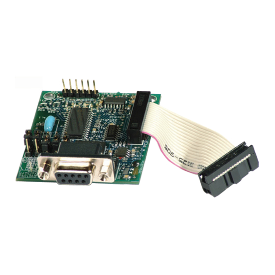
Baud Rate
Jumpers J1 to J3 set the serial port's baud rate.
9600 baud
The default setting is
baud rate of the controlling equipment. If a
different baud rate is required, set the jumpers
according to the diagram below:
DEFAULT
SETTING
9600 baud
J1 J2 J3
2400 baud
J1 J2 J3
300 baud
J1 J2 J3
Handshaking
RS-232C serial communication between
equipment sometimes requires flow
control (or "handshaking"), to confirm that
transmitter (the controller) and receiver
(the CDI-S100 in this case) are correctly
synchronised. PCB jumpers J4 and J5 control
handshaking.
Handshaking may be via "hardware",
"software", or off. Hardware handshaking
is also referred to as "RTS/CTS", and needs
additional pins of the 9-pin serial connector
to be wired (see "Pinout" on page 7).
Software handshaking is also referred to as
"Xon/Xoff".
off
The default setting is
If the controlling equipment requires
handshaking, set the jumpers according to the
following illustration:
. Check the
4800 baud
J1 J2 J3
1200 baud
J1 J2 J3
(no handshaking).
Mechanical fitting and internal
connection
If retrofitting the CDI-S100 to an existing
CX462 installation, turn the CX462 off,
remove its IEC mains lead and all its other rear
panel connections (marking as necessary to
assist re-connection). If the CX462 is mounted
in a rack, remove it.
If fitting the CDI-S100 to a new CX462,
unpack the CX462.
In either case, place the CX462 on a flat
surface, with the rear of the unit facing you.
1.
Undo the six screws securing the top
panel of the CX462; remove the panel.
Retain the screws.
2.
Remove the plastic blanking plate which
covers the serial interface module
connector hole in the rear panel. This is
held in place with adhesive and can be
prised off.
3.
Identify the empty 16-pin header labelled
CON7 on the main PCB just behind the
empty serial connector hole. Note there
is an M3 screw immediately behind this
connector, and another about 40 mm to
the right. Both these screws are clearly
marked with arrows; remove and retain
them.
CDI-S100 Installation Guide v1.0
5