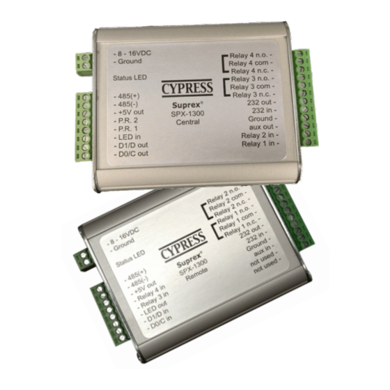
Cypress Suprex SPX-1300 Посібник з експлуатації - Сторінка 9
Переглянути онлайн або завантажити pdf Посібник з експлуатації для Подовжувач Cypress Suprex SPX-1300. Cypress Suprex SPX-1300 17 сторінок. Reader extender
Також для Cypress Suprex SPX-1300: Посібник з експлуатації (16 сторінок)

5. To activate the relay on the Remote unit connect as shown below. These connections can be used to allow the
Remote relay to operate a DOOR STRIKE, GATE, or other locking hardware. Refer to following pages in this
document for details of each I/O operation and connection. The Relay inputs are active LOW and will activate the
relay when connected to ground.
There are two relays available for accessory outputs at the Remote end. Either relay can be used to provide the Door
Strike or Gate activation function. This example uses Relay 1.
Access Control
Panel
LED OUT
Typical Access Control Panel Connection to activate Door Strike and reader LED.
Strike follows LED
Only Relay and LED Connections are shown for clarity, refer to previous diagrams for
Power,Data and communications connections.
Access Control
Panel
LED OUT
STRIKE
Typical Access Control Panel Connection to activate Door Strike and reader LED. Strike
follows separate panel output.
Suprex Operation and Initial Setup
Central Side Basic Panel Connections
2-8 to 16 VDC In
1-Ground
8-485(+)
7-485(-)
Central Unit
6-+5 VDC Out
5-Prog Res 2
*
4-Prog Res 1
3-LED Input
2-D1/Data/F2F Out
1-D0/Clock Out
1-D0/CLK Output
2-8 to 16 VDC In
1-Ground
8-485(+)
7-485(-)
Central Unit
6-+5 VDC Out
5-Prog Res 2
*
4-Prog Res 1
3-LED Input
2-D1/Data/F2F Out
1-D0/Clock Out
1-D0/CLK Output
12-RLY4 N.O.
11-RLY4 Com
10-RLY4 N.C.
9-RLY3 N.O.
8-RLY3 Com
7-RLY3 N.C.
6-RS232 Out
5-RS232 In
4-Ground
3-Aux Out
2-Relay2 Input
1-Relay1 Input
12-RLY4 N.O.
11-RLY4 Com
10-RLY4 N.C.
9-RLY3 N.O.
8-RLY3 Com
7-RLY3 N.C.
6-RS232 Out
5-RS232 In
4-Ground
3-Aux Out
2-Relay2 Input
1-Relay1 Input
