Ekinex EK-HE1-TP Handbuch - Seite 2
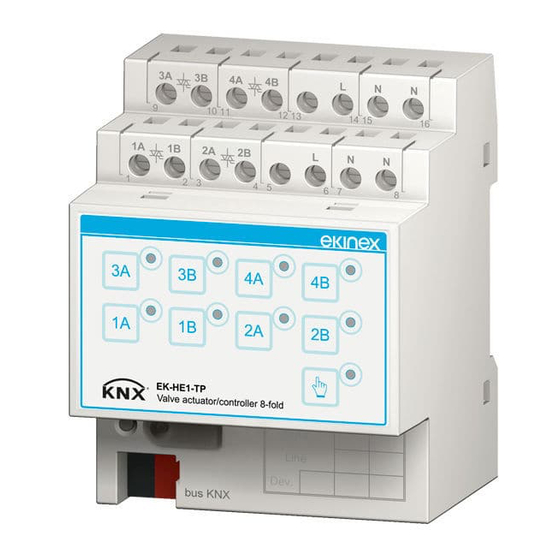
Blättern Sie online oder laden Sie pdf Handbuch für Controller Ekinex EK-HE1-TP herunter. Ekinex EK-HE1-TP 5 Seiten. Actuator / controller for electrothermal actuators

Technical data
Power supply
• 30 Vdc from bus (electronics)
• 230 Vac 50/60 Hz or 24 Vac (loads)
• Current consumption from bus < 30 mA
• Power consumption from bus 720 mW
TRIAC outputs
• Nr: 8 independent (2-pipe systems)
4 coupled (4-pipe systems)
• Max current I
: 2(1) A
max
• Max 4 electrothermal actuators in parallel for each
TRIAC output 0,5(0,3) A max
Environmental conditions
• Operating temperature: 0 ... + 55°C
• Storage temperature: - 25 ... + 55°C
• Transport temperature: - 25 ... + 70°C
• Relative humidity: 95% not condensing)
i
Note. For controlling loads different than electro-
thermal drives and servomotors for zone valve or
loads with rated current higher than the maximum
current, interface relays must be used.
Switching, display and connection elements
The device is provided with a membrane front keypad
with signalling LEDs and pushbuttons, programming LED
and pushbutton, a terminal for connecting the KNX bus
line and screw terminals for connecting the power supply
and the outputs.
3A
3B
4A
9
10
11
1A
1B
2A
1
2
3
1
2
3
bus KNX
1) Programming pushbutton
2) Programming LED
3) Terminal block for KNX bus line
4) Field for physical address
Membrane keypad
5
6
5) Signalling LED for xy channel (x = 1 ... 4; y = A, B)
6) Pushbutton for manual operation of xy channel (x = 1 ... 4; y = A, B)
7) Pushbutton for switching manual / automatic operation
8) LED for signalling manual / automatic operation mode
4B
L
N
N
12
13
14
15
16
2B
L
N
N
4
5
6
7
8
Area
4
Line
Dev.
8
7
i
Note. To switch between manual mode and auto-
matic mode (and vice versa), press the appropriate
pushbutton for a time > 3 s.
Signalling LED
LED
Status
on
Single channel
off
Group of 4
slow blinking
channels
(1 s)
fast blinking
Single channel
(1 / 4 s)
on
Pushbutton ma-
nual / automatic
off
*) To acknowledge a short-circuit alarm, keep pressed the correspon-
ding channel pushbutton for a time > 3 s.
i
Note. Use only servomotors for zone valve equip-
ped with stroke-end microswitches.
Terminal blocks for power supply and outputs
3A
3B
4A
9
10
11
1A
1B
2A
1
2
3
Nr.
Sign
Connection
1
1A
TRIAC output for valve drive
2
1B
TRIAC output for valve drive
3
2A
TRIAC output for valve drive
4
2B
TRIAC output for valve drive
9
3A
TRIAC output for valve drive
10
3B
TRIAC output for valve drive
11
4A
TRIAC output for valve drive
12
4B
TRIAC output for valve drive
6, 14
L
Power supply phase (230 Vac or 24 Vac)
7, 8, 15, 16
N
Power supply neutral (230 Vac or 24 Vac)
Mounting
The device has degree of protection IP20, and is there-
fore suitable for use in dry interior rooms. The housing
is made for rail mounting according to EN 60715 in bo-
ards or cabinets for electrical distribution. The correct
mounting is when the KNX bus terminal is located at the
bottom. When installing be sure to leave accessible only
the front panel; all other sides must not be accessible.
For the installation of the device on the rail proceed as
follows:
• with the aid of a tool bring the locking device in the fully
lowered position (1);
• place the upper edge of the rear inner profile on the
upper edge of the rail (2);
2
Meaning
Presence of power supply
Absence of power supply
Absence of power supply for a
4-channels group
Short-circuit alarm*
Manual mode active
Automatic mode active
4B
L
N
N
12
13
14
15
16
2B
L
N
N
4
5
6
7
8
