AMERITRON ALS-500RC Betriebsanleitung - Seite 2
Blättern Sie online oder laden Sie pdf Betriebsanleitung für Kontrolleinheit AMERITRON ALS-500RC herunter. AMERITRON ALS-500RC 4 Seiten.

PORT B
Port B allows operation of the Frequency Select Switch and the PWR LED.
CONNECTIONS
1. Place the ALS-500RC in a convent location at your operating station.
2. Plug one of the supply patch cords into port A of the remote head and note
which color was used. Route the other end of the same cable to the
amplifier and plug into Remote A.
Switch is off.
3. Connect the other supply patch cable into port B. Route the other end to the
amplifier and plug into Remote B. Make sure the amplifier's Frequency
Select Switch is in the Remote position.
4. The ALS-500RC's Relay Jack operates the same as the amplifier's Relay
Jack. Use the ALS-500RC's relay jack (RLY) or the Amplifier's Relay
Jack, whichever makes installation easier.
Instruction Manual for operation of the relay jack.
OPERATION
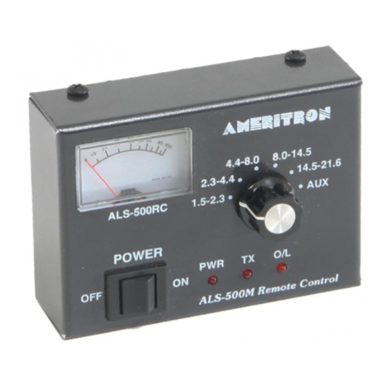
The controls on the ALS-500RC serve the same function as the controls on front
of the Amplifier. The Amplifier's Power switch must be in the off position and
the Frequency Select Switch in the Remote position.
Set the ALS-500RC's Frequency switch to the same frequency as the
transceiver.
When the ALS-500RC switch is turned on the meter and power light should
illuminate.
When the transceiver is placed into transmit the TX light should illuminate and
current meter should deflect.
The O/L light will illuminate when the amplifier reaches a VSWR that is too
high or the frequency switch is in the wrong position. Placing the power switch
off and back on will reset the O/L light.
Make sure the amplifier's Power
Refer to the Amplifier's
2
