Dormakaba 5750-K Installationshandbücher - Seite 5
Blättern Sie online oder laden Sie pdf Installationshandbücher für Intercom System Dormakaba 5750-K herunter. Dormakaba 5750-K 9 Seiten. Electronic entry device
Auch für Dormakaba 5750-K: Bedienungsanleitung für den Benutzer (2 seiten), Bedienungsanleitung für den Benutzer (2 seiten)
dormakaba
DEAD/SPRING BOLT
1. Mount the dial plate (p/n 2676) centered on the through hole. Attach the dial plate
with the two mounting screws US 8-32 (US) or the M4-0.7 (metric), and the shoulder
bushings
(p/n 2618).
2. Measure total mounting thickness (door thickness + mounting plate). (Figure 3)
3. Cut the spindle to a length of .700" (17mm) plus the total mounting thickness.
NOTE: the spindle must be deburred.
4. Insert the spindle into the keypad, and route the cable in the groove of the spindle.
5. Slide the bearing plate (p/n 2674) over the cable, and press onto the fasteners on the
Entry Device.
NOTE: It is important to make sure the cable will not rub on the dial plate after
assembly.
6. Feed the Entry Device's cable and spindle through the spindle/cable hole from the
front of the safe door.
WARNING: Spring and blocking pin are NOT installed when Entry Device is used with
either the dead bolt or spring bolt locks.
7. Rotate the key pad approx. 30° counter-clockwise and place onto the bushings.
8. Then turn the key pad clockwise until the key pad is vertical (Figure 4).
DOOR
Figure 3
Total Mounting Thickness = door thickness
+ mounting plate
9. The spindle should protrude between .300" - .350" (8 - 9 mm) through the safe door.
10. Slide the cable protector (p/n 2754) over the cable and spindle, until the flat side rests against
the inside of safe door. Route the cable through the groove of the cable protector.
11. Gently pull on the cable to assure that there is no excess cable in the spindle hole that would rub
on the metal door.
12. Install the lock with the bolt extended onto the spindle.
INSTALLING BATTERIES
The 3035/3125 Entry Device require either a battery box (2788 or 4001), or a battery/alarm box
(2789 or 4002) to provide power to the lock.
NOTE: The 3125 Entry is not UL listed. The Battery and Battery/Alarm boxes have not been UL
evaluated.
Mount the battery box inside the safe, and connect the cable coming from the battery box directly
into the connector port marked BAT on the lock.
Small Battery and Battery/Alarm Box:
1. Open safe door.
2. Remove battery box cover by pulling the front portion away from the safe door.
CAUTION! Hold onto the battery connector to avoid pulling the wires out of the board.
3. Connect a new 9-Volt alkaline battery to the battery connector.
4. Push the battery and the leads completely into the battery compartment.
5. Replace the cover and test the lock several times before closing the door.
(P/N) 762.128 Rev G 05/17 • © copyright 2009-2018
Figure 4
Cable
protector
3125
3035 & 3125 Entry Device
(Dead Bolt/Spring Bolt Option)
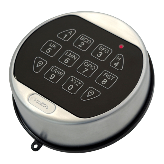
1. Key Pad
2. Bearing Plate
3. Mounting Screws
4. Shoulder Bushing
Battery
compartment
2788 Small Battery Box or
2789 Small Battery Alarm Box
4001 Large Battery Box
4002 Large Battery
Alarm Box
5. Dial Plate
6. Spindle
7. Cable Protector
4