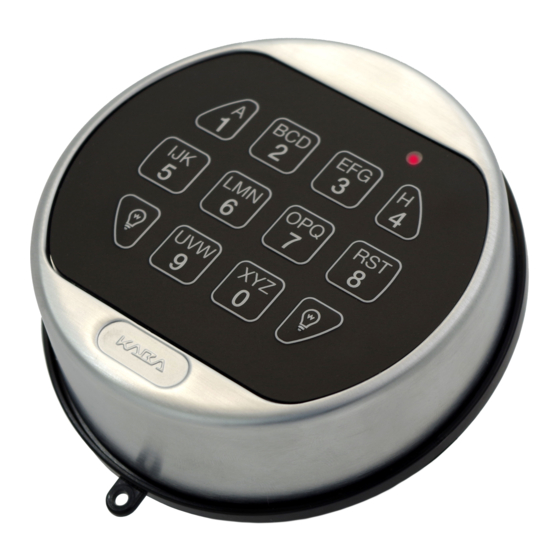
Dormakaba 5750-K Installationshandbücher - Seite 7
Blättern Sie online oder laden Sie pdf Installationshandbücher für Intercom System Dormakaba 5750-K herunter. Dormakaba 5750-K 9 Seiten. Electronic entry device
Auch für Dormakaba 5750-K: Bedienungsanleitung für den Benutzer (2 seiten), Bedienungsanleitung für den Benutzer (2 seiten)

dormakaba
DEAD BOLT/SPRING BOLT
1. Mount the dial plate to safe (p/n 3752) centered on the through hole (Figure 5). Attach the dial plate with the two
mounting screws US 8-32 or the M4-0.7 (metric) making sure to rotate the dial plate counter clockwise prior to
tightening down.
NOTE: The spindle must be deburred but not rounded off.
2. Insert the spindle into the keypad, making certain it is fully seated; route the cable in the groove of the spindle
(Figure 9).
3. Slide the bearing plate over the cable and spindle, and press onto the fasteners on the Entry Device.
4. Feed the Entry Device's cable and spindle through the spindle/cable hole from the front of the safe door.
WARNING: Spring and blocking pin are NOT installed when Entry Device is used with either the dead bolt or spring bolt
locks.
5. DO NOT USE BLOCKING PINS or SPRINGS. Rotate the keypad approximately 30º counter-clockwise and guide the
keypad bushings into the large openings on the dial plate.
6. Then, turn the keypad clockwise until it is vertical.
7. Mark the spindle protruding through the safe door and mounting plate to be cut so that .354" (9mm) will be protruding
after cutting to length.
8. Rotate the keypad approximately 30º and remove from dial plate.
9. Remove spindle and cut as marked in Step 7.
10. Reassemble keypad, spindle, and bearing plate.
11. Skip this step if the battery door is to be removable. Otherwise, attach the battery door to the keypad, by first inserting
the hinge pin into the hole on the battery door and then insert the battery door with hinge pin into the hinge pin hole on
the keypad housing (adjacent to the locking pin hole - Figure 7). DO NOT USE BLOCKING PINS or SPRINGS.
CAUTION: If the battery door is to stay permanently attached, the hinge pin must be inserted before the keypad is
secured to the dial plate (step 12). With a Dead bolt or Spring bolt lock, once the keypad is fully installed, the hinge pin
cannot be added or removed from the safe door without removing the lock first.
12. Rotate the keypad approximately 30º counter-clockwise and guide the keypad bushings into the large openings on the
dial plate. Then, turn the keypad clockwise until it is vertical.
13. The spindle should protrude .354" (9mm) through the safe door. Slide the cable protector over the cable and spindle
until the flat side rests against the inside surface of the safe door.
14. Gently pull on the cable to ensure there is no excess cable in the spindle/cable hole.
15. Route the cable through the indention of the cable protector and install the lock with bolt extended onto the spindle.
Refer to lock installation instructions which are available at www.dormakaba.us.
Figure 9 - Dead Bolt lock installation.
Optional
Hinge Pin
(P/N) 762.128 Rev G 05/17 • © copyright 2009-2018
6
