AMS AS5600 Betriebshandbuch - Seite 4
Blättern Sie online oder laden Sie pdf Betriebshandbuch für Kontrolleinheit AMS AS5600 herunter. AMS AS5600 12 Seiten. 12-bit programmable contactless potentiometer
Auch für AMS AS5600: Handbuch (14 seiten), Benutzerhandbuch (13 seiten), Betriebshandbuch (10 seiten)

AS5600-SO_RD_ST
Operation Manual
Table 2:
Adapter Board Pin-Out (J1)
Pin
Symbol
Description
1
VDD
Positive Power Supply
2
OUT
Output Pin
3
DIR
Direction input
4
PGO
Programming Mode
5
SDA
I2C Data
6
SCL
I2C Clock
7
GND
Ground
Table 3:
Adapter Board Pin-Out (J2)
Pin
Symbol
Description
1
VDD
Positive Power Supply
2
OUT
Output Pin
7
GND
Ground
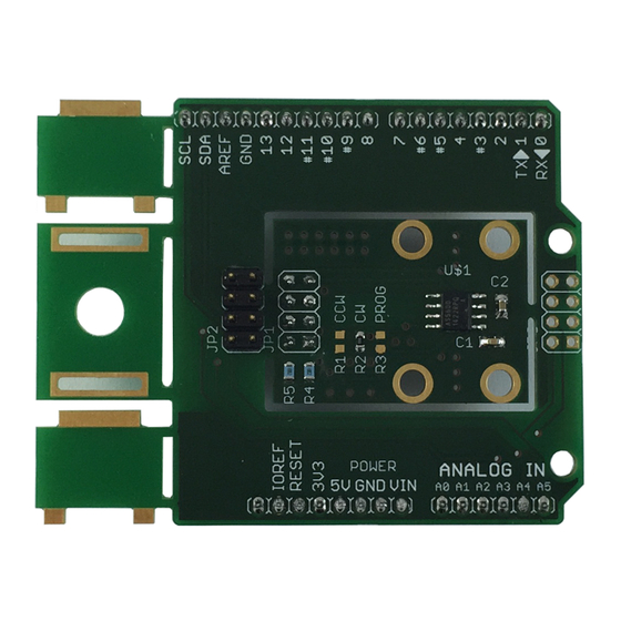
2.2 Adapter Board Description
The AS5600 is connected over the 7-way header or by using the 3-Wire Mode. Connect the desired
pins of the AS5600 using the headers and resistors.
www.ams.com
Info
Analog Output default, PWM possible, Is used
for programming option B
CCW default. Pulled to GND using R2. Remove
R2 and insert at R1 for CCW direction.
Pull to GND using R4 for Programming Option B
(refer to the datasheet)
Info
Analog Output default, PWM possible, Is used
for programming option B
Revision 1.1 / 30.06.2014
page 4/11
