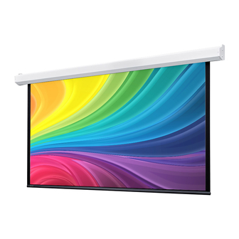
Draper Targa XL Anleitung Installation & Betrieb - Seite 3
Blättern Sie online oder laden Sie pdf Anleitung Installation & Betrieb für Projektionsfläche Draper Targa XL herunter. Draper Targa XL 8 Seiten. Electric projection screen 220v

Premier XL / Targa XL 220V
Section 2 - Hanging Screen
General:
1. Screen should be lifted into position only by end mounting brackets. Keep case level
by lifting end plates simultaneously to prevent surface damage. Never attempt to lift
screen along its length.
3. When locating viewing surface and checking clearance for screen's operation,
remember surface is centered in case. Handle case carefully to protect its finish.
4. Regardless of mounting method, screen should be positively and securely supported
so that vibration or even abusive pulling on viewing surface will not cause case to loosen
or fall. Installer must ensure that fasteners used are of adequate strength and suitable for
mounting surface chosen.
Ceiling and Wall Installation:
CAUTION: Product is very heavy: Installer must provide adequate attachment hardware
and anchors as required. Installer must also ensure that structure is of adequate strength.
CAUTION: Case must be mounted low enough from ceiling to gain access to
bracket screws.
Please Note: Do not use a power screwdriver to tighten screw. Maximum torque for
tightening screw is 5 nm.
Section 3 - Operation
Please Note: Before fully operating screen: For Targa, remove tape; on Premier, lower viewing surface enough to fully expose shipping brackets, then remove
shipping brackets by loosening screws, removing end shipping brackets, sliding center shipping brackets off dowel, and re-tightening screws
220V Single Station Control — 3-position up-off-down switch permits operation to be stopped at any point. Factory adjusted limit
switches automatically stop screen when fully down or fully up.
220V Multiple Station Control — Switches similar in appearance to 220V Single Station Control. Screen stops when switch is released
and may be restarted in either direction. Factory adjusted limit switches stop screen automatically when fully down or fully up.
For LVC-IV Controls:
24V Control — Three-button up-stop-down switch
sequence. Factory adjusted limit switches automatically stop screen when fully down or fully up.
1. The key-operated power supply switch controls power to unit and switches. When it is "off",
switches will not operate. Key may be removed from switch in either "on" or "off" position.
2. A three-position key switch permits screen to be operated directly by key. In this case,
screen operator must always have a key.
RS232 / Ethernet — Serial communication and network communication available.
Plug & PlayTM — Supplied with a 9'8"
Screen is equipped with a handheld remote or 3-position operating switch.
Three positions
permit operation to be stopped at any point.
(up-off-down)
Factory adjusted limit switches automatically stop screen when fully down or fully up.
Section 4 - Tab-Tension Adjustment Procedure
Please Note: The Draper Tab-Tensioning System is factory-set, and under
normal circumstances will not require field adjustment. If wrinkles are observed,
however, follow the adjustment procedure
stop at any point desired, operate in any
(es)
cable lead. No wiring is necessary.
(2.9m)
.
(Fig. 4)
CAUTION: Do not touch or bend surface.
Motor Retaining
Screw
(included)
CAUTION: Do not remove the roller assembly from the case
unless necessary for repairs. If the roller assembly is removed,
be sure motor is fully re-seated in the bracket, and re-secure it
carefully with the motor retaining spring and screw.
END OF
DOWEL
Figure 4
PUSH & TURN
COUNTER-CLOCKWISE
to RELEASE TENSION
page 3 of 8
Figure 2
MOTOR RETAINING
SPRING AND
SCREW
.
(Fig. 3)
Figure 3
END OF
DOWEL
PUSH & TURN
CLOCKWISE
to INCREASE TENSION
