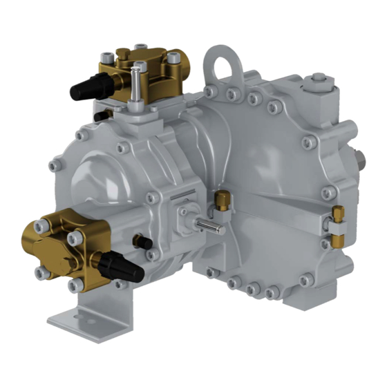
Carlyle 05T-033 Anwendungshandbuch - Seite 8
Blättern Sie online oder laden Sie pdf Anwendungshandbuch für Kompressor Carlyle 05T-033 herunter. Carlyle 05T-033 20 Seiten. Screw compressor

2.6 Mechanical Unloading
All Carlyle screw compressors are equipped with one step
of mechanical unloading. The unloader valve is controlled
by a solenoid mounted on the compressor body. The com-
pressor is unloaded when the solenoid is de-energized
and loaded when the solenoid is energized. The compres-
sor should always be started unloaded (for a minimum time
determined by the control module) which will provide a soft
start by partially relieving the compression chamber back to
suction. Unloaded operation reduces the effective capacity
by 30% to 62%, depending on the model and system condi-
tion (see tables below).
ESTIMATED PERCENTAGE UNLOADING
BY MODEL
50HZ OPERATION
COMPRESSOR
06TR
MODEL
MODELS
06T—033
62%
06T—039
61%
06T—044
60%
06T—048
59%
06T—054
58%
06T—065
55%
06T—078
50%
06T—088
47%
06T—108
45%
Capacity
Control
The 05T/06T screw compressors can be run unloaded con-
tinually without affecting the reliability of the compressor.
2.7
High Discharge Pressure Control
A high pressure cut out must protect the compressor from
exceeding 350 psig (25.2 bar). The compressor may be
brought back online after the discharge pressure falls below
300 psig (21.4 bar). The maximum pressure differential
8
60HZ OPERATION
06TA
06TR
06TA
MODELS
MODELS
MODELS
52%
60%
51%
59%
50%
58%
49%
56%
48%
55%
45%
50%
40%
45%
37%
40%
—
—
Vi Control
(05/06TR only)
(discharge-suction) is 350 psi. The internal pressure relief
valve will open if the pressure differential exceeds 400 psi
(+/-3%).
2.8 Low Suction Pressure Cut Out
A low suction pressure cut out must protect the compressor
from operating below 10 inches of vacuum pressure. Each
compressor must be individually protected with a low pres-
sure switch connected to the low side access port. The
compressor may be brought back online after a 3 minute
delay.
2.9 Volume Index (Vi) Control
All low temperature models (05TR/06TR) are supplied with
a Vi control valve that allows for two Vi settings (see chart
below). This dual Vi allows for optimum efficiency over a
wide range of head pressures. The Vi must be set to low
(solenoid de-energized) during start-up for a minimum of 30
seconds. The Vi may then be set as desired for optimum en-
ergy efficiency. The following table reflects the operational
50%
recommendations for the Vi control. Carlyle also recom-
49%
mends the use of a small deadband at this change-over
48%
point to avoid unnecessary short cycling of the Vi solenoid.
46%
The LonCEM
45%
ing pressure ratio and controls Vi output accordingly. The
40%
older CEM requires external controls to accomplish the
35%
same task.
30%
Compressor
—
Model
06TR
06TA
2.10 Reverse Rotation Protection
Correct compressor rotation is critical for compressor reli-
ability. The compressor can fail within 2 seconds of start-up
if it is not rotating in the correct direction. Installation of a
pressure gage at the discharge pressure access fitting in
the compressor body (measuring the pressure upstream of
the integral discharge check valve) is recommended during
initial start-up or whenever the compressor is serviced. The
gage should be monitored to ensure increasing discharge
pressure at start-up.
The LonCEM protection module uses a pressure sensor to
monitor the discharge pressure change at startup to ensure
proper compressor rotation. The LonCEM module elimi-
nates the need for a mechanical low-pressure switch and
line/load phase monitor. See Appendix A for descriptions of
operation applications for the LonCEM module.
2.11 Mufflers
Screw compressors emit gas pulsations result in radiated
noise from the discharge line and oil separator. The addition
of a muffler is required in all applications to reduce dis-
charge line and oil separator noise levels. The muffler
should be located within 6-inches (15cm) of the compressor
discharge service valve.
®
controller continuously monitors the operat-
System
Vi
Pressure Ratio
setting
>5.0
High:4.0
<5.0
Low: 2.8 De-energized
Fixed:
All
2.8
Solenoid
State
Energized
—
