CommScope Argus CV3PX Installationsanleitung Handbuch - Seite 2
Blättern Sie online oder laden Sie pdf Installationsanleitung Handbuch für Antenna CommScope Argus CV3PX herunter. CommScope Argus CV3PX 7 Seiten. 353mm (13.9”) profile panel antennas
Instruction Manual, 353mm (13.9") Profile Panel Antennas
Installation Instructions
Ensure a torque spanner is used when tightening fasteners, see the mounting kit
diagrams on the following pages for the correct torque recommendations.
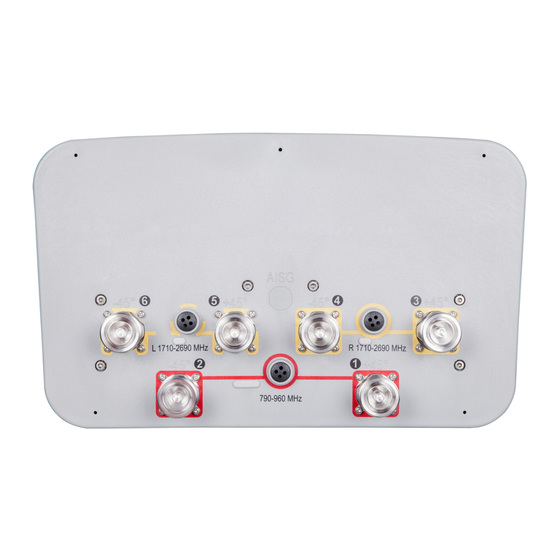
Ensure antenna is installed with the connectors at the bottom.
Installation Instructions – Adjustable Downtilt Mounting Kit
T-029-GL-E, T-041-GL-E, T-045-GL-E, T-095-GL-E
Assemble mounting kits as per Figure 2 and 3 of this document.
1. Attach the mounting kit assembly to the antenna, before trying to clamp
2. Downtilt angles in 1° increments can be obtained with the correct
The clamp brackets can clamp pipe diameters between 50 mm (2") & 115mm
(4.5"). For typical installations of antennas up to 1575mm (62") long the minimum
recommended pipe diameter is 60mm (2.4"). For antennas over 1575mm (62")
long the minimum recommended pipe diameter is 75mm (3").
Upper Mounting Bracket Assembly
( To Suit Pipes OD 75-115 mm)
Figure 1: Correctly Assembled Mounting Kit Using Clamp Bracket for Mechanically
the brackets to the pole.
adjustment of the tilt arm bracket.
Downtilt can be achieved by aligning the corresponding hole in the
•
tilt arm to the pivot bracket which mates against the mounting pole, as
shown in Figure 4. The first hole is for 1° downtilt*, with each consecutive
hole resulting in an increased inclination of 1°.
(*Note for the T-045-GL-E kit the tilt is 0° then 2° - 10° in 1° steps.
For the T-095-GL-E kit the tilt starts at 0° and increments in 3° steps)
For finer downtilt angle adjustments the distance in between the top
•
and bottom mounting bracket on the pole can be adjusted.
For 0° downtilt the tilt arm may be stowed as show in Figure 4.
•
An inclinometer or other angular measuring device may be used to
•
verify downtilt angle as required.
Adjustable Downtilt Antenna
Bulletin A997-0083Revision F February 2014 page 2 of 7
Lower Mounting Bracket Assembly
(To Suit Pipes OD 75-115 mm)