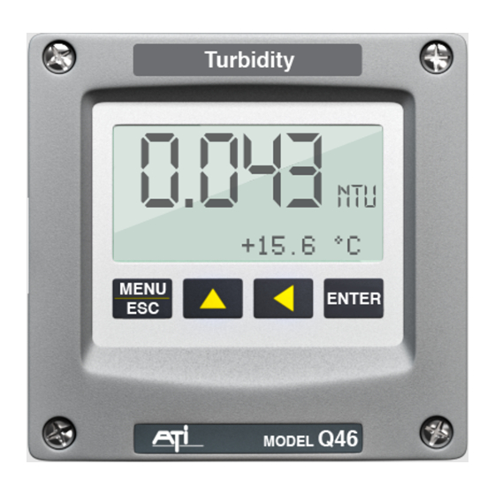
ATI Technologies Q46N Handbuch Kommunikation - Seite 4
Blättern Sie online oder laden Sie pdf Handbuch Kommunikation für Messgeräte ATI Technologies Q46N herunter. ATI Technologies Q46N 18 Seiten.

ATI
Q46 Ethernet/IP Communications Manual
1.3
Ethernet/IP Transmission Details
It should be understood that Ethernet/IP is simply an application layer protocol
that is transferred over an Ethernet hardware link. The word "Ethernet" simply
refers to the common physical cable, perhaps running to an office PC.
In the OSI model, "Ethernet" is the lower part of the model, the physical transfer
method or the hardware.
transferred, which is specified near the top of the OSI model. In the common
office network, many different standard communication protocols are operating
during normal office use, like IP, TCP, etc. None of these are designed to handle
the CIP industrial format, so that interface must be handled by a specific program
that recognizes the format. Because of this, an Ethernet/IP device cannot be
directly connected to your office network for transferring information.
The data for the protocol is constructed into a specific structure inside a standard
TCP/IP Packet. A user application program simply decodes the structure inside
the received TCP or UDP packet. The data structure consists of a grouping of
data values called Attributes inside other sets of containment data called Objects.
There are Ethernet/IP required Objects and application Objects. Required
objects are typically - Identity, TCP, and Router. Application objects consist of
some defined data types, like a Motor Object, and some user specific data
types.
1.4
Ethernet/IP Card Installation Instructions
Use the following instructions to install the Ethernet/IP Communications Option
into an existing Q46 Analyzer. Monitors ordered with the Ethernet option will be
supplied with the board already installed.
1. Disconnect power to the Q46 prior to installation of the board.
2. Remove the connector cover on the power supply circuit board located next to
the fuse.
3. Carefully plug the Ethernet/IP circuit board into the connector on the power
supply board.
4. Align the cover board holes with the holes in the circuit board and use the screws
supplied to secure the assembly. Refer to Figure 1 on the next page for the
proper assembly.
It says nothing about the way information is
4
