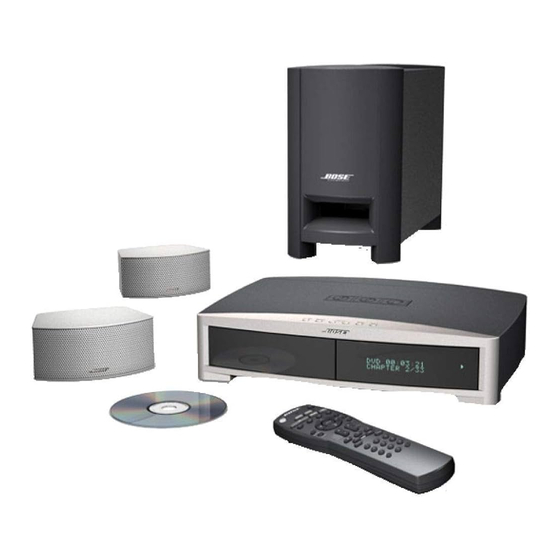
Bose 3-2-1 Handbuch zur Fehlersuche
Blättern Sie online oder laden Sie pdf Handbuch zur Fehlersuche für Home Theater System Bose 3-2-1 herunter. Bose 3-2-1 28 Seiten. Home entertainment system
Auch für Bose 3-2-1: Benutzerhandbuch (44 seiten), Handbuch zur Schnelleinrichtung (1 seiten)
Safety Information ..................................................................................................................................... 2
Electrostatic Discharge Sensitive (ESDS) Device Handling .................................................................. 3
Theory of Operation ............................................................................................................................. 4-26
System Overview ...................................................................................................................................... 4
Console Theory of Operation .............................................................................................................. 4-19
1.0 Power Supply ...................................................................................................................................... 4
1.1. Switching Power Supplies .............................................................................................................. 5
1.2. Linear Power Supplies ..................................................................................................................... 5
1.3. Supply Synchronization .................................................................................................................. 5
1.4. Power Failure Detection .................................................................................................................. 6
2.0 Processor and Its Peripherals ............................................................................................................ 6
3.0 Communications Busses and Interface Blocks ............................................................................... 8
3.1 Communications Busses ................................................................................................................. 8
3.2 Interface Blocks ................................................................................................................................ 9
3.3 Ethernet ............................................................................................................................................ 10
4.0 Audio Path .......................................................................................................................................... 11
4.1 Analog Audio Path ........................................................................................................................... 12
4.2 Digital Audio Path ............................................................................................................................ 12
4.3 Interaction Between the Digital and Analog Inputs ...................................................................... 13
5.0 Video Path .......................................................................................................................................... 13
6.0 Tuner Electronics .............................................................................................................................. 14
6.1 Main PCB Interface ......................................................................................................................... 14
6.2 Control ............................................................................................................................................. 15
6.3 FM Tuner .......................................................................................................................................... 16
6.5 Phase-locked Loop Tuning ............................................................................................................. 18
6.6 RDS ................................................................................................................................................... 19
PS3•2•1 Series II Speaker System (Bass Module) Theory of Operation ............................................. 19
1.0 Components ...................................................................................................................................... 19
2.0 Bass Module Interface ...................................................................................................................... 19
2.1 Interface connector and cable descriptions ................................................................................. 20
2.2 3•2•1 Series II Bass Module Details ............................................................................................... 21
Test Procedures ................................................................................................................................. 27-36
Console Procedures ........................................................................................................................ 27-33
Bass Module Procedures ................................................................................................................ 34-35
Satellite Array Procedures .................................................................................................................... 36
Appendix ............................................................................................................................................. 37-51
Figure 1. 3•2•1 Series II Console Test Setup Diagram ............................................................................ 37
Figure 2. 3•2•1 Series II Bass Module Test Setup Diagram .................................................................... 38
Obtaining System Information from the Media Center Display ........................................................ 39
Computer Setup Procedure ............................................................................................................ 40-41
TAP Cable Construction ....................................................................................................................... 42
Boselink ETAP Cable Wiring Diagram ................................................................................................. 42
B+B Electronics model 232LPTTL RS232 to TTL converter .............................................................. 42
Bass Module Test Cable Construction ................................................................................................ 43
Bass Module Test Cable Wiring Information ...................................................................................... 43
Console Test Cable Construction ........................................................................................................ 44
Console Test Cable Wiring Information .............................................................................................. 44
Putting the Console into TAP mode .................................................................................................... 45
Console TAP Commands ................................................................................................................. 45-48
Changing the Region Code .................................................................................................................. 49
Console Troubleshooting Tips ............................................................................................................. 50
Bass Module Troubleshooting Tips ..................................................................................................... 51
IC Diagrams ........................................................................................................................................ 52-61
Service Manual Revision History ........................................................................................................... 62
CONTENTS
1