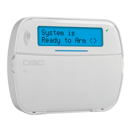
DSC HS2LCDWF v1.0 Installationsanleitung Handbuch - Seite 2
Blättern Sie online oder laden Sie pdf Installationsanleitung Handbuch für Tastenfeld DSC HS2LCDWF v1.0 herunter. DSC HS2LCDWF v1.0 9 Seiten. Wireless keypad

Installation Instructions
The HS2LCDWF wireless keypad is compatible
with the HS2016/32/64 and HS2128 PowerSeries
Neo wireless panels.
Specifications
• Temperature range: -10°C to +55°C (14°F to 131°F)
UL/ULC: 0°C to +49°C (32°F to 120°F)
• Humidity (MAX): 93%R.H. non-condensing
• Plastic enclosure protection degree: IP30, IK04
• Power adaptor output voltage: 9.0V
els - US/Latin America: xx; Canada:
xx; AUS./NZ:
xx;
China: xx limited power supply,
acceptable to the authority having jurisdiction
• Battery: 4 AA, 1.5 V, Energizer alkaline consumer-
grade
• Low Battery Indication: 4.3 V
• HS2LCDWF current draw: 50mA
• Wall-mount tamper
• 5 programmable function keys
• Ready (Green LED), Armed (Red LED), Trouble/RF
Jam (Red/Yellow LED), AC (Green LED)
• Frequency: 433.92MHz
(xx only/xx only)
• Frequency: 868.35MHz
(xx only)
• Frequency: 915MHz
(xx only)
• Up to 128 wireless zones
NOTE: DSC recommends that the keypad be powered by
the AC adaptor and the batteries for EN installations.
When the power adaptor is used, batteries provide mini-
mum 24h back-up.
Unpacking
The HS2LCDWF keypad package is available in
five distinct configurations, described below
The keypad contains patented technology for the
Proximity (Prox) Tag.
HS2LCDWF - wall mount HS2LCDWFP - prox tag
• 1 HS2LCDWF keypad • 1 HS2LCDWF keypad
• 1 HS2LCDWF wall
• 1 HS2LCDWF wall
bracket
bracket
• 1 Installation Manual
• 1 Installation Manual
• 1 inner door sticker
• 1 inner door sticker
• 4 AA batteries
• 4 AA batteries
• 1 hardware pack
• 1 hardware pack
• 1 prox tag
HS2LCDWFPV - prox
tag w/ verbal
annunciation
• 1 HS2LCDWFBRK wall
bracket
• 1 Installation Manual
• 1 inner door sticker
• 1 power adaptor
• 4 AA batteries
• 2 hardware packs
• 1 prox tag
HS2LCDWFPV - prox tag w/ verbal
@ 1.25A. Mod-
DC
annunciation, transformer and deskstand
xx;
EU: xx; UK:
• 1 HS2LCDWFBRK wall
bracket
• 1 Installation Manual
• 1 inner door sticker
• 1 power adaptor
• 4 AA batteries
• 2 hardware packs
• 1 prox tag
Mounting
Mount the keypad where it is accessible from desig-
nated points of entry and exit. Once a dry and secure
location has been selected, perform the following
steps to mount the keypad.
Wall Mounting Plate
1. Locate the screw holes (4) at each corner of the
mounting plate.
2. Use the four screws provided to affix the mount-
ing plate to the wall; ensure the mounting tabs
are facing you (see diagram below). If the keypad
is to be mounted on drywall, use plastic anchors
.
(not supplied).
3.Align the four mounting slots in the HS2LCDWF
housing with the four mounting tabs protruding
from the mounting plate.
4. Slide the keypad into place.
5. Firmly but carefully snap the keypad down onto
HS2LCDWFPV - prox
tag w/ verbal annuncia-
tion and transformer
• 1 HS2LCDWFBRK wall
bracket
• 1 Installation Manual
• 1 inner door sticker
• 1 power adaptor
• 4 AA batteries
• 2 hardware packs
• 1 prox tag
• 1 transformer
Desk Stand -
HS2LC-
• 1 transformer
DWFDMK
•1 HS2LCDWFDMK desk
1. Insert the four rub-
stand
2. Place the desk stand on a secure, uncluttered sur-
3.Align the four mounting slots in the HS2LCDWF
4. Slide the keypad into place. Firmly but carefully
5. To fasten the keypad securely onto the desk
Apply Battery Power
1. Slide the keypad up and out from the mounting
2. Insert the batteries as directed on the back of the
3. Replace the keypad on the mounting plate/desk
the mounting plate.
Mounting tab
Mounting tab
Screw hole
Mounting tab
Screw hole
ber feet (found in
the hardware pack)
into the indentations
provided in the bot-
tom of the desk
stand.
face.
housing with the four mounting tabs protruding
from the desk stand.
snap the keypad down onto the desk stand.
stand, locate the hole in the centre of the bottom
of the desk stand. Using the screws provided,
screw the keypad to the desk stand.
plate/desk stand (removing the screws first if
required). The bay for the four AA batteries is
open and visible at the back of the keypad.
keypad. Ensure the correct polarity is observed.
stand.
Screw hole
Mounting tab
Screw hole
