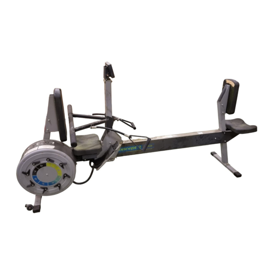
concept 2 DYNO Montageanleitung Handbuch - Seite 3
Blättern Sie online oder laden Sie pdf Montageanleitung Handbuch für Fitnessgeräte concept 2 DYNO herunter. concept 2 DYNO 12 Seiten.

DYNO ASSEMBLY INSTRUCTIONS
1.
Open the three boxes and remove all the parts. Lay out the parts as shown
below before beginning assembly. Call Concept2 if any parts are missing.
Parts List
1 Monorail Assembly PN5100
2 Flywheel Assembly
3 Carriage Assembly
4 Force Monitor Assembly
5 Push Side Foot Assembly PN5130
6 Pull Side Foot PN5131
7 Pull Side Leg PN5122
8 Push Side Seat Assembly
11
8
Fastener List
A. (2) Bolt - 3/8 by 3 1/2"
B. (6) Bolt - 3/8 by 2 5/8"
C. (4) Screw - 3/8 by 7/8"
D. (12) Bolt - 3/8 by 5/8"
E. (8) Nut - 3/8" lock nut
F .
(2) Screw - 1/4 by 2 1/2"
G. (2) Nut - 1/4"
H. (4) Phillips head screw #10 by 1/2"
I.
(4) Connector plate spacers
J. (4) #10 lock washers
11/01
13
15
4
1
2
9
Pull Side Seat PN5401
10 Pull Side Seat Brackets
11 Push Side Seat Back Bracket PN5106
12 Pull Side Seat Back Bracket PN5103
13 Push Side Seat Back PN5403
14 Pull Side Seat Back PN5402
15 Handlebar Assembly PN5118
16 (2) Pull handles PN5720
17 Bungee Cord
3
16
17
5
A.
I.
1
(left PN5101 and right PN5102)
12
14
9
7
10
6
D.
E.
B.
F .
G.
C.
J.
H.
