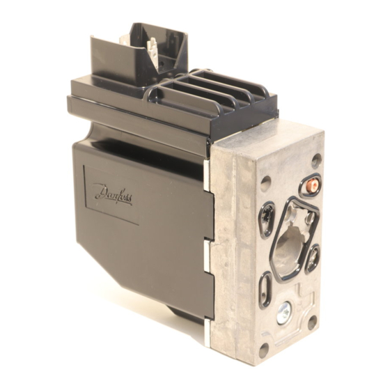
Danfoss PVEU-F Installationshandbuch - Seite 4
Blättern Sie online oder laden Sie pdf Installationshandbuch für Controller Danfoss PVEU-F herunter. Danfoss PVEU-F 8 Seiten. Electrical actuating module for pvg 32 and pvg 100

Proportional
Standard PVE with SP
Version
Connection PVE with Spool Position (SP)
Connector
Deutsch
Control (U
Function
Neutral
Q: P → A
Q: P → B
PVE with separate Float pin
Connection PVEH with float A six pin
Connector
AMP
Deutsch
Control (U
pin version
Function
Neutral
Q: P → A
Q: P → B
Float
PWM controled PVE – PVEP
Connection PVEP
Connector
Deutsch
Control (U
Function
Neutral
Q: P → A
Q: P → B
4
U
Error
SP
S
p 1
p 2
p 4
) for standard mounted PVES-SP
S
U
S
0,5 • U
DC
0,5 → 0,25 • U
DC
0,5 → 0,75 • U
DC
U
(control)
U
S
pin 1
pin 1
) for standard mounted PVEH/PVEM float A six
S
Voltage relative
0,5 • U
DC
0,5 → 0,25 • U
DC
0,5 → 0,75 • U
DC
U
on Float pin
DC
PWM A
Error
PWM B
p 1
p 2
p 3
) for standard mounted PVEP
S
PWM A
< 10%
10% → 80%
< 10%
520L0619 • Rev EB • Mar 2014
Gnd
U
DC
p 5
p 6
Not
connected
PWM
Error
50%
U s
50% → 25%
50% → 75%
(power)
Float
DC
pin 2
pin 5
pin 6
pin 3
PWM
50%
Not con-
50% → 25%
nected
50% → 75%
Float
Error
Deutsch version with separate float pin
Float
Error
Gnd
U
DC
p 5
p 6
PWM B
< 10%
< 10%
10% → 80%
PVES-SP
Deutsch version PVES–SP
4
3
5
2
6
1
U
Ground
Error
pin 3
pin 4
pin 5
pin 2
AMP with separate float pin
PVEH-F
No con-
nection
4
3
5
2
6
1
U s
U
157-779
Deutsch version with PVEP
© Danfoss, 2014-03
LED
Spool position
DC
LED
LED
DC
LED
