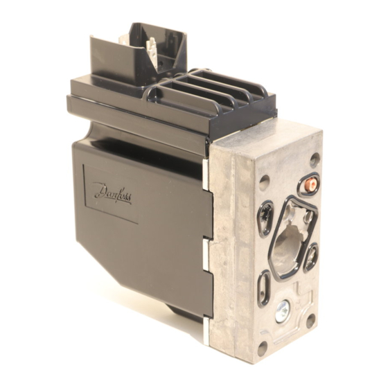
Danfoss PVEU-F Installationshandbuch - Seite 6
Blättern Sie online oder laden Sie pdf Installationshandbuch für Controller Danfoss PVEU-F herunter. Danfoss PVEU-F 8 Seiten. Electrical actuating module for pvg 32 and pvg 100

Technical data
Følgende tekniske data bygger på typiske testresultater. Der anvendes mineralsk olie med en viskositet på
21 mm
The following technical data are from typical test results. For the hydraulic system a mineral based
hydraulic oil with a viscosity of 21 mm
Folgende technische Daten bauen auf typische Testergebnisse. Es wurde Mineralöl mit einer Viskosität
von 21 mm
Les caractéristiques techniques suivantes sont tirées de résultats de tests typiques. Pour le système
hydraulique, on a utilisé une huile minérale d'une viscosité de 21 mm
de 50°C [122°F].
PVEO, PVEM
Supply voltage U
Current consumption at rated voltage
Signal voltage (PVEM)
Signal current at rated voltage (PVEM)
Input impedance in relation to 0.5 • U
Power consumption
PVEA, PVEH, PVEP, PVES, PVEU
Supply voltage U
Current consumption
at rated voltage
Signal voltage
Signal current at rated voltage
Input impedance in relation to 0.5 • U
Input capacitor
Power consumption
Oil viscosity
Oil
viscosity
Bemærk: Maksimum opstartsviskositet
Note: Max. start up viscosity 2500 mm
Beachte: Maximale Viskosität bei Inbetriebnahme
Remarque : Viscosité maximale au démarrage 2500 mm
Filtering in the hydraulic system
Required
operating
cleanliness level
Bemærk: I særligt udsatte maskiner anbefales der beskyttelse med en skærm.
Beachte: In besonders ausgesetzten Maschinen wird Schutz in Form von
elektrischer Abschirmung empfohlen.
NB: In particularly exposed applications, protection by screen is recommended.
Remarque: Pour les applications particulièrement exposées, il est recommandé
d'installer une protection par écran.
6
/s [102 SUS] og en temperatur på 50°C [122°F].
2
/s [102 SUS] und einer Temperatur von 50°C [122°F] verwendet.
2
DC
rated / range
DC
max. ripple
PVEH/PVEP/PVES/PVEU (PVEA)
PVEA/PVEH/PVES - neutral
PVEA/PVEH/PVES - A-port ↔ B-port
PVEU - neutral
PVEU - A-port ↔ B-port
PVEP - neutral
PVEP - A-port
PVEP - B-port
PVEH/PVEP/PVES/PVEU (PVEA)
12 – 75 mm
range
/s
2
[65 – 347 SUS]
min.
4 mm
/s [39 SUS]
2
max.
460 mm
/s [2128 SUS]
2
/s
2
18/16/13
(ISO 4406, 1999 version)
520L0619 • Rev EB • Mar 2014
/s [102 SUS] and a temperature of 50°C [122°F] were used.
2
rated
12 V DC
range
11 V to 15 V
max. ripple
5%
0.65 A @ 12 V
neutral
0.5 x U
DC
A-port ↔ B-port
0.25 • U
0.25 mA
12 KΩ
DC
8 W
11 V to 32 V
5%
0.57 (0.28) A @ 12 V
0.5 x U
DC
0.25 • U
5V
2.5V to 7.5V
A< 10%, B < 10%
10%<A<80%, B< 10%
A< 10%, 10%<B<80%
0.25 mA to 0.70 mA
12 KΩ
DC
100 ηF
7 (3.5) W
Oil temperature
Oil
temperature
Operating temperature
Ambient
Stock
Recommended long
time storage in
/s
packaging
2
Pilot pressure
Pilot pressure
(relative to T
pressure)
Grade of enclosure
Connector version
AMP JPT
Hirschmann
Deutsch
* According to the international standard IEC 529.
/s [102 SUS] et à une température
2
24 V DC
22 V to 30 V
0.33 A @ 24 V
to 0.75 • U
DC
DC
0.50 mA
0.3 (0.15) A @ 24 V
to 0.75 • U
DC
DC
range
30 – 60˚C [86 – 140˚F]
min.
-30˚C [-22˚F]
max.
90˚C [194˚F]
-30 – 60˚C [-22 – 140˚F]
-40 – 90˚C [-40 – 194˚F]
10 – 30˚C [50 – 86˚F]
nom.
13.5 bar [196 psi]
min.
10 bar [145 psi]
max.
15 bar [217 psi]
*
IP 66
IP 65
IP 67
© Danfoss, 2014-03
