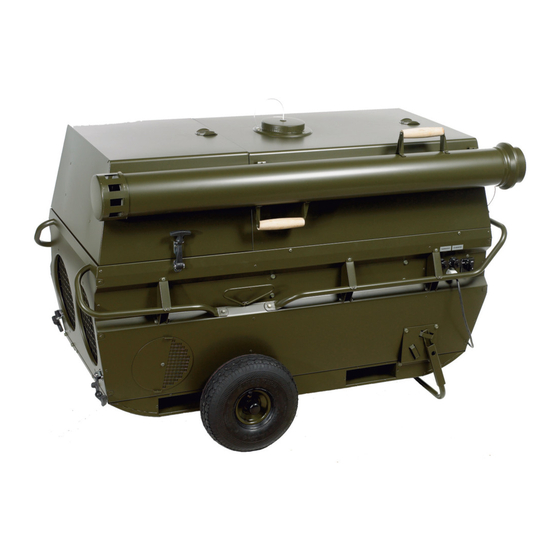
Dantherm VA-M40 MKII Service-Handbuch - Seite 17
Blättern Sie online oder laden Sie pdf Service-Handbuch für Klimageräte Dantherm VA-M40 MKII herunter. Dantherm VA-M40 MKII 20 Seiten.

Control system,
Room thermostat
The room thermostat (accessory) will be placed inside the tent, to control the room
temperature. The wanted temperature will be set on the thermostat. If the temperature
falls below the set point the thermostat will automatically start up the burner. After
reaching the set point the thermostat automatically shuts off the burner of the unit
again.
See also "Set-up", page 23 (Thermostat) for further explanation.
CO monitor
The CO monitor (accessory) will be placed inside the tent nearby the warm air distribu-
tion duct. The CO monitor is factory set and will stop the complete unit if the CO con-
tent in the air is higher than the set point of the monitor. At the same time the monitor
will give an acoustical signal.
See also "Set-up", page 23 (CO-monitor) for further explanation.
Internal fan/limit
The internal fan thermostat control delays fan operation until the discharge air tem-
thermostat
perature has reached the preset factory temperature of 60 °C. This means that the fan
will not operate after burner start before the heat exchanger is heated to this tempera-
ture. After the burner stopped the fan will continue to operate and cool the heat ex-
changer/combustion chamber until the air discharge temperature has fallen to approx-
imately 30 °C.
The limit thermostat automatically stops the burner if the air discharge temperature ex-
ceeds 80 °C. The fan will continue. When the temperature has fallen by approximately 5
°C, then the burner will automatically switch on again.
Overheat protec-
The overheat thermostat operates when the heat exchanger is in danger of being dam-
tion
aged from an excess of temperature. This thermostat protector shuts down the fuel, ig-
nition and air supply systems. The red OT indicator lamp on the internal control box il-
luminates.
Follow this procedure to reset the system (after determining the fault):
Burner flameout
A flameout protector built in into the burner, activates when the burner flame is abnor-
protection
mal or unstable. This safety device automatically shuts off the fuel flow, ignition and
combustion air supply. The red reset button on the burner control box illuminates.
LED lights
There are four LED lights on the inside control panel which are indicating the state of
the unit:
CO override
OT failure
continued
LED
Color
Yellow
Red
Indication
Illuminates if no CO monitor is connected
Illuminates if the sensor in the heat exchanger registers
a temperature higher than the set point for this sensor.
In this case the unit will stop totally and can only be
started again after having pressed the reset button on
the OT thermostat
Continued overleaf
17
