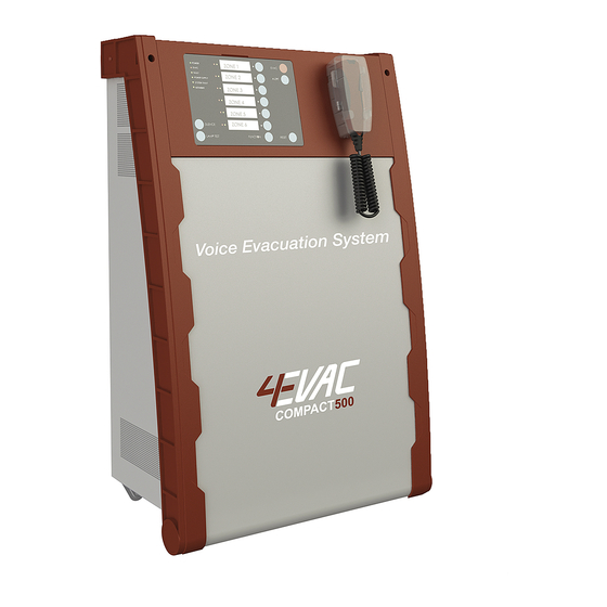
4EVAC Compact 500 Betriebshandbuch - Seite 2
Blättern Sie online oder laden Sie pdf Betriebshandbuch für Sicherheitsausrüstung 4EVAC Compact 500 herunter. 4EVAC Compact 500 15 Seiten. Voice evacuation system

Hacousto Holland bv
Industrieweg 87
2651BC Berkel & Rodenrijs
4EVAC Compact 500 operation manual
Table of Contents
1. What does Compact 500 do? ............................................................................................................................................. 3
2. Configuration settings ........................................................................................................................................................... 3
3. Standalone vs network operation ...................................................................................................................................... 4
Standalone system ........................................................................................................................................................ 4
Network system.............................................................................................................................................................. 4
3.2.1. Global network (G-Net) ................................................................................................................................. 4
3.2.2. Local network (L-Net) .................................................................................................................................... 5
4. Front Panel ................................................................................................................................................................................. 6
LED indicators ................................................................................................................................................................. 6
4.1.1. POWER ................................................................................................................................................................ 6
4.1.2. EVAC .................................................................................................................................................................... 6
4.1.3. FAULT ................................................................................................................................................................... 7
4.1.4. POWER SUPPLY ................................................................................................................................................ 7
4.1.5. SYSTEM FAULT .................................................................................................................................................. 7
4.1.6. NETWORK ........................................................................................................................................................... 7
4.1.7. Zone indicators ................................................................................................................................................ 8
Manual controls ............................................................................................................................................................. 9
4.2.1. SILENCE ............................................................................................................................................................... 9
4.2.2. LAMP TEST ......................................................................................................................................................... 9
4.2.3. ZONE selection ................................................................................................................................................. 9
4.2.4. RESET ................................................................................................................................................................... 9
4.2.5. FUNCTION button ........................................................................................................................................... 9
5. Integrated fireman mic ......................................................................................................................................................... 10
6. KEY switch ................................................................................................................................................................................. 10
7. Technical specifications ........................................................................................................................................................ 11
8. Marking ...................................................................................................................................................................................... 13
Page 2 of 15
Author:
DD
