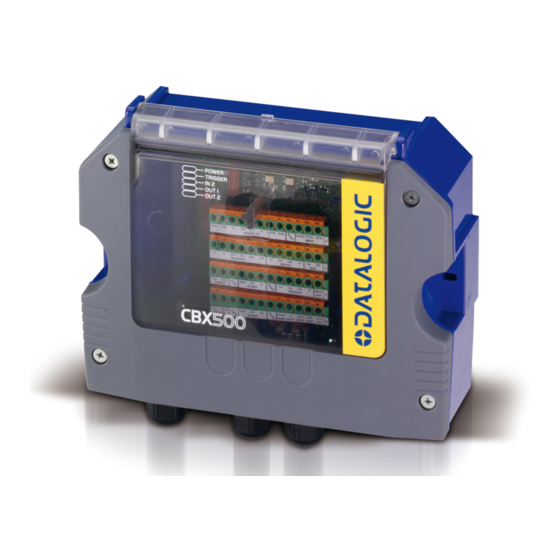
Datalogic CBX500 Installationshandbuch - Seite 6
Blättern Sie online oder laden Sie pdf Installationshandbuch für Barcode-Leser Datalogic CBX500 herunter. Datalogic CBX500 17 Seiten. Scanning connection box
Auch für Datalogic CBX500: Installationshandbuch (16 seiten), Installationshandbuch (17 seiten)

CBX500 INSTALLATION MANUAL
OPENING THE CBX500
To install the CBX500 or during normal maintenance, it is necessary to open it by unscrewing
the four cover screws:
CAUTION: The CBX500 must be disconnected from the power supply
during this operation.
MECHANICAL INSTALLATION
CBX500 can be mounted to various wooden or plastic surfaces using the two self-threading
screws (3.9 x 45 mm) and washers provided in the package.
Mounting to other surfaces such as concrete walls or metallic panels requires user-supplied
parts (screws, screw anchors, nuts, etc). A mounting template is included in the package to
facilitate hole drilling alignment.
CBX500 can also be mounted to a DIN rail using the BA100 (93ACC1821) mounting
accessory or to a Bosch Frame or 80/20 Frame using the BA200 (93ACC1822) mounting
accessory.
The diagram below gives the overall dimensions of the CBX500 and shows the two mounting
through-holes.
180
[7.1]
6
Mounting
Holes
mm
in
Figure 1 - Overall Dimensions
80.9
4
[3.18]
[0.16]
82.9
[3.26]
